
- Texas Instruments Floating Point Digital Signal Processor Specification Sheet


SPRS292A − OCTOBER 2005 − REVISED NOVEMBER 2005
26
POST OFFICE BOX 1443 • HOUSTON, TEXAS 77251−1443
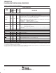
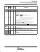
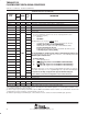
Terminal Functions (Continued)
SIGNAL
PIN
NO.
TYPE
†
IPD/
‡
DESCRIPTION
SIGNAL
NAME
GDP/
ZDP
TYPE
†
IPD/
IPU
‡
DESCRIPTION
HOST-PORT INTERFACE (HPI)
HINT J20 O IPU Host interrupt (from DSP to host)
HCNTL1 G19 I IPU Host control − selects between control, address, or data registers
HCNTL0 G18 I IPU Host control − selects between control, address, or data registers
HHWIL H20 I IPU Host half-word select − first or second half-word (not necessarily high or low order)
HR/W G20 I IPU Host read or write select
HD15 B14 IPU
Host-port data
•
Used for transfer of data, address, and control
HD14
§
C14 IPU
• Used for transfer of data, address, and control
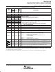
• Also controls initialization of DSP modes at reset via pullup/pulldown resistors
− Device Endian mode (HD8)
HD13
§
A15 IPU
− Device Endian mode (HD8)
0 – Big Endian
1 − Little Endian
HD12
§
C15 IPU
1 − Little Endian
EMIF Big Endian mode correctness (EMIFBE) (HD12)
HD11 A16 IPU
EMIF Big Endian mode correctness (EMIFBE) (HD12)
0 – The EMIF data will always be presented on the ED[7:0] side of the bus,
regardless of the endianess mode (Little/Big Endian).
HD10 B16 IPU
regardless of the endianess mode (Little/Big Endian).
1 − In Little Endian mode (HD8 =1), the 8-bit or 16-bit EMIF data will be
present on the ED[7:0] side of the bus.
HD9 C16 IPU
present on the ED[7:0] side of the bus.
In Big Endian mode (HD8 =0), the 8-bit or 16-bit EMIF data will be present
on the ED[31:24] side of the bus [default].
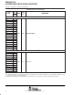
HD8
§
B17
I/O/Z
IPU
on the ED[31:24] side of the bus [default].
This new functionality does not affect systems using the curent default value of HD12=1. For
HD7 A18
I/O/Z
IPU
This new functionality does not affect systems using the curent default value of HD12=1. For
more detailed information on the big endian mode correctness, see the EMIF Big Endian Mod
e
Correctness portion of this data sheet.
HD6 C17 IPU
Correctness portion of this data sheet.
− Bootmode (HD[4:3])
HD5 B18 IPU
− Bootmode (HD[4:3])
00 – HPI boot/Emulation boot
01 − CE1 width 8-bit, Asynchronous external ROM boot with default timings
HD4
§
C19 IPD
00 – HPI boot/Emulation boot
01 − CE1 width 8-bit, Asynchronous external ROM boot with default timings
(default mode)
10 − CE1 width 16-bit, Asynchronous external ROM boot with default timings
HD3
§
C20 IPU
(default mode)
10 − CE1 width 16-bit, Asynchronous external ROM boot with default timings
11 − CE1
width 32-bit, Asynchronous external ROM boot with default timings
HD2 D18 IPU
11 − CE1 width 32-bit, Asynchronous external ROM boot with default timings
Other HD pins (HD [15:13, 11:9, 7:5, 2:0]) have pullups/pulldowns (IPUs/IPDs). For proper de-
HD1 D20 IPU
Other HD pins (HD [15:13, 11:9, 7:5, 2:0]) have pullups/pulldowns (IPUs/IPDs). For proper de-
vice operation of the HD[14, 13, 11:9, 7, 1, 0], do not oppose these pins with external IPUs/IPD
s
at reset; however, the HD[15, 6, 5, 2] pins can be opposed and driven during reset.
HD0 E20 IPU
at reset; however, the HD[15, 6, 5, 2] pins can be opposed and driven during reset.
For more details, see the Device Configurations section of this data sheet.
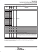
HAS E18 I IPU Host address strobe
HCS F20 I IPU Host chip select
EMIF − CONTROL SIGNALS COMMON TO ALL TYPES OF MEMORY
¶
HDS1 E19 I IPU Host data strobe 1
HDS2 F18 I IPU Host data strobe 2
†
I = Input, O = Output, Z = High impedance, S = Supply voltage, GND = Ground, A = Analog signal (PLL Filter)
‡
IPD = Internal pulldown, IPU = Internal pullup. [To oppose the supply rail on these IPD/IPU signal pins, use external pullup or pulldown resistors
no greater than 4.4 kΩ and 2.0 kΩ, respectively.]
§
To ensure a proper logic level during reset when these pins are both routed out and 3−stated or not driven, it is recommended an external 10-kΩ
pullup/pulldown resistor be included to sustain the IPU/IPD, respectively.
¶
To maintain signal integrity for the EMIF signals, serial termination resistors should be inserted into all EMIF output signal lines.