
- Texas Instruments Floating Point Digital Signal Processor Specification Sheet


SPRS292A − OCTOBER 2005 − REVISED NOVEMBER 2005
30
POST OFFICE BOX 1443 • HOUSTON, TEXAS 77251−1443
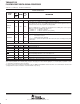
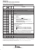
Terminal Functions (Continued)
SIGNAL
PIN
NO.
TYPE
†
IPD/
‡
DESCRIPTION
SIGNAL
NAME
GDP/
ZDP
TYPE
†
IPD/
IPU
‡
DESCRIPTION
MULTICHANNEL BUFFERED SERIAL PORT 1 (McBSP1) (CONTINUED)
DR1 M2 I IPU
Receive data
On this device, this pin does not have an internal pullup (IPU). For proper device operation,
the DR1 pin should either be driven externally at all times or be pulled up with a 10-kΩ resis-
tor to a valid logic level. Because it is common for some ICs to 3-state their outputs at times, a
10-kΩ pullup resistor may be desirable even when an external device is driving the pin.
DX1 L2 O/Z IPU Transmit data
FSR1 M3 I/O/Z IPD Receive frame sync
FSX1 L1 I/O/Z IPD Transmit frame sync
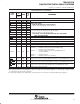
MULTICHANNEL BUFFERED SERIAL PORT 0 (McBSP0)
CLKS0 K3 I IPD External clock source (as opposed to internal)
CLKR0 H3 I/O/Z IPD Receive clock
CLKX0 G3 I/O/Z IPD Transmit clock
DR0 J1 I IPU Receive data
DX0 H2 O/Z IPU Transmit data
FSR0 J3 I/O/Z IPD Receive frame sync
FSX0 H1 I/O/Z IPD Transmit frame sync
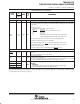
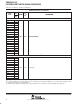
GENERAL-PURPOSE INPUT/OUTPUT (GPIO) MODULE
CLKOUT2/
GP[2]
Y12 I/O/Z IPD
For this device, the CLKOUT2 pin is multiplexed with the GP[2] pin.
Clock output at half of device speed (O/Z) [default] (SYSCLK2 internal signal
from the clock generator) or this pin can be programmed as GP[2] (I/O/Z).
When the CLKOUT2 pin is enabled, the CLK2EN bit in the EMIF global control
register (GBLCTL) controls the CLKOUT2 pin (All devices).
CLK2EN = 0: CLKOUT2 is disabled
CLK2EN = 1: CLKOUT2 enabled to clock [default]
GP[7](EXT_INT7) E3
General-purpose input/output pins (I/O/Z) which also function as external
interrupts
GP[6](EXT_INT6) D2
I/O/Z
IPU
General-purpose input/output pins (I/O/Z) which also function as external
interrupts
Edge-driven
GP[5](EXT_INT5) C1
I/O/Z IPU
•
Edge-driven
•
Polarity independently selected via the External Interrupt Polarity Register
GP[4](EXT_INT4) C2
•
Polarity independently selected via the External Interrupt Polarity Register
bits (EXTPOL.[3:0]), in addition to the GPIO registers.
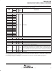
†
I = Input, O = Output, Z = High impedance, S = Supply voltage, GND = Ground, A = Analog signal (PLL Filter)
‡
IPD = Internal pulldown, IPU = Internal pullup. [To oppose the supply rail on these IPD/IPU signal pins, use external pullup or pulldown resistors
no greater than 4.4 kΩ and 2.0 kΩ, respectively.]