
Laptop User Manual


A - 4 VC5090 Vehicle Computer Product Reference Guide
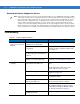
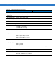
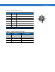
Table A-3 USB Connector Pin-Outs
Pin Signal Description
1 USB+ USB positive signal
2 USB- USB negative signal
3 Vcc 5 VDC USB power (500 mA)
4 GND Ground
5 HPWR Keyboard heater
6 BLEN Backlight enable signal
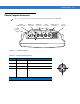
Mating connector: Amphenol p/n C091-31D006-100-2
P1
P2
P5
P3
P4
P6
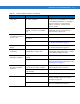
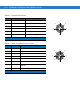
Table A-4 COM1 and COM2 Connector Pin-Outs
Pin Signal Description
1 RxD Serial data input to VC5090
2 TxD Serial data output to VC5090
3 RTS Request To Send output from VC5090
4 CTS Clear To Send input to VC5090
5 DCD Data Carrier Detect input to VC5090
6 DTR Data Terminal Ready output from VC5090
7 Ext Vcc 5 VDC switched power output to peripherals
(500 mA)
8 GND Ground
Mating connector: Amphenol p/n C091-31D008-100-2
P1
P4
P3
P2
P5
P6P7
P8