VC6000 Series Quick Reference Guide
© 2008 MOTOROLA, INC. All rights reserved. Motorola reserves the right to make changes to any product to improve reliability, function, or design. Motorola does not assume any product liability arising out of, or in connection with, the application or use of any product, circuit, or application described herein.
Quick Reference Guide 1 Introduction The Motorola VC6000 Series is a rugged vehicle computer, specifically designed for the harsh conditions of the mobile environment. The VC6000 Series enables real-time data access, collection, capture and report of information related to the driver’s workflow, status and location. In indoor applications, the VC6000 Series serves as a stationary office computer for communication and control of outdoor VC6000 Series.
2 VC6000 Series Vehicle Computers About this Guide This guide contains the following: • Model Configurations on page 2 • Features on page 4 • Unpacking on page 6 • Optional Accessories on page 6 • Installation on page 7 • Operating the VC6000 Series on page 17 • Troubleshooting on page 20 • Regulatory Information on page 20 For more information, refer to the VC6000 Series Product Reference Guide, p/n 6802986C08-x available at: www.motorola.com/enterprisemobility/manuals.
Quick Reference Guide 3 The VC6000 Series features: • Ergonomic design with a color LCD touch screen • Windows Mobile 6.1 operating system • Internal Bluetooth radio to enable wireless connection to a Bluetooth printer, bar code scanner, headset and other Bluetooth peripherals • Connection to WLAN in 802.
4 VC6000 Series Vehicle Computers Features Front Features 1 2 15 3 14 4 13 5 6 12 11 10 7 9 8 1. Power Button with System Indication LED1 9. Call or Home key4 2. Two green LEDs driven by application2 3. Volume up/down key (6 levels) 4. Brightness up/down key 5. Microphone 6. Full QWERTY keypad 10. End or Back key5 11. Navigation key 12. Select key 13. Speaker (embedded) 7. Left soft key3 14. Function keys6 15. Touch screen 8. Right soft key3 1 See “System Indication LED” on page 17.
Quick Reference Guide 5 Back Features 14 13 12 11 10 9 8 1 2 3 1. PWR - Power connector 2. GPS antenna connector 3. WWAN antenna connector 4. WLAN antenna connector1 5. Mini USB port, type B2 6. USB port, type A2 7. 10/100 Ethernet port2 4 5 6 7 8. Auxiliary port2, 3 9. SIM card slot2 10. SD memory card slot2 11. USB port, type A2 12. M4 screw mounting bosses 13. M4 Ground screw boss 14. Cable Retention Bracket 1 Reverse thread - rotate counterclockwise to fasten connector.
6 VC6000 Series Vehicle Computers Unpacking The following items are contained inside the shipping box: • VC6000 Series • Hardware Kit (including five M4 installation screws) • This guide 3 NOTE A hardware kit that contains optional accessories is provided separately inside the shipping box.
Quick Reference Guide 7 Installation Installing a SIM Card (VC6096 only) Before using the VC6096 in a cellular network, make sure that the VC6096 is equipped with a Subscriber Identity Module (SIM) card, obtained form your service provider. The SIM card is a small smart card that fits into the VC6096. The SIM card holds the personalized information about the VC6096, including network activation and phone book entries. To install the SIM card: 1.
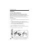
8 VC6000 Series Vehicle Computers Installing an SD Memory Card A Secure Digital (SD) memory card provides secondary non-volatile data storage. MMC and non-SDHC SD memory cards can be used. The card slot is located on the side panel of the VC6000 Series. To install the SD memory card: 1. Lift up the Protective Rubber Cap that covers the Memory Card Slot. 2. Position the SD Memory Card with the contacts facing the back of the VC6000 Series and insert into the Memory Card Slot.
Quick Reference Guide 9 • When fixing a conduit or a cable on the outside of a vehicle, use P-Clips. Either drill and tap the hole or use a nut and bolt to secure the clip. • Ensure the cable does not have tight bends. The minimum recommended radius is 6.35 cm (2.5 inches). • Ensure cables do not swing or chafe on the structure. This often requires using cable ties approximately every one foot, and ensuring the cables do not flex often, especially where they connect to the VC6000 Series.
10 VC6000 Series Vehicle Computers 5. Connect and turn clockwise to lock the Power Plug to Power Connector (PWR) of the VC6000 Series (See Back Features on page 5). The length of the cable is 3 m (9.8 ft.). Vehicle Power Cable Power Plug 10 A Fuse SLO BLO Black Wire Fuse Holder Red Wire Green Wire Shrink Tubing 6. When routing wires, slide Shrink Tubing over wires as required. 7. Connect the power terminals of the Vehicle Power Cable to the terminals of the vehicle battery.
Quick Reference Guide 11 2. Plug connectors J2 and J3 to the telemetry receptacles of your vehicle data bus. 3. Connect the I/O Wires as required. Telemetry Cable J2 - RS232 Connector J1 - To VC6000 Series Auxiliary port I/O Wires: 8 digital inputs, 8 digital outputs, 2 analog inputs, Debug (2 wires for debugging). See label on wires. Maximum current through wires 0.
12 VC6000 Series Vehicle Computers CAUTION To avoid damage to the VC6096, make sure to disconnect the power cable from the VC6096 before connecting the antenna cable. When installing the antenna cable, make sure to connect the antenna side of the cable before connecting to the VC6096. Installation guidelines: 1. For best performance, it is recommended to install the antenna outside of the cabin. When installing the antenna in the vehicle cabin or indoors, keep a minimum distance of 70 cm (2.3 ft.
Quick Reference Guide 13 Mounting the GPS Antenna (VC6096 only) The VC6096 is supplied with an internal module of Global Positioning System (GPS). Connect the cable connector of the GPS antenna to the GPS connector at the back of the VC6096. CAUTION To avoid damage to the VC6096, make sure to disconnect the power cable from the VC6096 before connecting the antenna cable. Installation guidelines: 1. Recommended GPS antenna - Motorola part number 8508851K59. 2.
14 VC6000 Series Vehicle Computers Connecting the VC6000 Series Indoor When using the VC6000 Series indoor, the VC6000 Series can be placed on a desk and powered using an Indoor Power Supply Unit. To connect the VC6000 Series indoor: 1. Connect a ground wire between the VC6000 Series and the facility ground system. WARNING: To ensure proper grounding, use a 18AWG ground wire between the VC6000 Series Ground Point (GND) and the facility ground system.
Quick Reference Guide 2. 15 Mount the Combination Antenna outdoors. Contact the mast of the antenna, by a metal bonding, to a ground wire that runs directly into the earth, via a deep ground rod. For antenna installation guidelines, See “Mounting the Combination Antenna (VC6096 only)” on page 11. WARNING! Keep a minimum lateral distance of 20 cm (8 inches) between the VC6000 Series user and the antenna.
16 VC6000 Series Vehicle Computers Optional Mounting The following mount examples should be used for installing the VC6000 Series inside the vehicle. For optional mounting instructions, refer to the documentation provided by the mount manufacturer. Recommended mount manufacturer: RAM Mounts. WARNING! Vehicles equipped with air bags - An air bag inflates with great force.
Quick Reference Guide 17 Operating the VC6000 Series System Indication LED The System Indication LED is located inside the Power Button (See Front Features on page 4). The System Indication LED indicates the following states: LED State Indication Off Normal operation Fast flashing amber • Critical power event. Input power is out of operating range. The VC6000 Series may turn off - save your entries. • Vehicle engine start - no action is required. • Cold reset is active - no action is required.
18 VC6000 Series Vehicle Computers Standby Mode Standby mode is a power saving mode enabled only when the vehicle ignition key is switched to the OFF position. In Standby mode, the screen display and backlight illumination automatically turn off after a period of two minutes when VC6000 Series is not active. Resume from Standby Mode To resume from Standby mode, press any key, or touch the screen, or momentarily press the Power Button Power Button .
Quick Reference Guide 19 Resetting the VC6000 Series If the VC6000 Series stops responding to inputs, perform the reset actions in the following order: Warm Boot Warm boot may become necessary when an application running on your VC6000 Series does not respond after performing initial reset. CAUTION Warm boot may cause lost of information from programs currently running on the computer. To perform warm boot: Press and hold the Power Button for five seconds and release.
20 VC6000 Series Vehicle Computers Troubleshooting Problem The VC6000 Series does not power on. Cause Solution Vehicle ignition key in OFF position. Switch on the vehicle ignition key to the ON position. SIM door is open. Close the SIM door properly and secure screw. Drained vehicle battery. Charge or replace battery. Power cable is disconnected. Connect the Power cable. Low Battery level warning is issued. Vehicle battery voltage dropped below 9 V DC.
Quick Reference Guide 21 This device is approved under Enterprise Mobility business of Motorola, Inc., (“Motorola”). Regulatory Information is available in English, French, German, Italian, Spanish, Turkish, Simplified Chinese. Local language translations are available at the following web site: www.motorola.com/enterprisemobility/manuals. This device is approved under the Motorola, Inc (“Motorola”).
22 VC6000 Series Vehicle Computers NOTE 2: The use of 5GHz RLAN's has varying restrictions of use; please refer to the Motorola Declaration of Conformity (DoC) for details. CAUTION Operation of the device without regulatory approval is illegal. Health and Safety Recommendations Ergonomic Recommendations CAUTION In order to avoid or minimize the potential risk of ergonomic injury follow the recommendations below.
Quick Reference Guide 23 An air bag inflates with great force. DO NOT place objects, including either installed or portable wireless equipment, in the area over the air bag or in the air bag deployment area. If in-vehicle wireless equipment is improperly installed and the air bag inflates, serious injury could result. Position your device within easy reach. Be able to access your device without removing your eyes from the road.
24 VC6000 Series Vehicle Computers and suspend conversations that have the potential to divert your attention from the road. 6. Use your wireless phone to call for help. Dial the Emergency services, (9-1-1 in the US, and 1-1-2 in Europe) or other local emergency number in the case of fire, traffic accident or medical emergencies. Remember, it is a free call on your wireless phone!. The call can be made regardless of any security codes and depending on a network, with or without a SIM card inserted. 7.
Quick Reference Guide 25 Other Medical Devices Please consult your physician or the manufacturer of the medical device, to determine if the operation of your wireless product may interfere with the medical device. FCC / EU RF Exposure Guidelines Safety Information The device complies with Internationally recognized standards covering Maximum Permissible Exposure (MPE) related to human exposure to electromagnetic fields from radio devices.
26 VC6000 Series Vehicle Computers Wireless Devices - Countries Country Roaming This device incorporates the International Roaming feature (IEEE802.11d) which will ensure the product operates on the correct channels for the particular country of use. Ad-Hoc Operation Ad-Hoc operation is limited to Channels 36-48 (5150-5250 MHz). Use of this band is restricted to Indoor Use Only, any other use will make the operation of this device illegal.
Quick Reference Guide 27 Radio Frequency Interference Requirements - Canada This Class B digital apparatus complies with Canadian ICES-003. Cet appareil numérique de la classe B est conforme à la norme NMB-003 du Canada. IMPORTANT: In the band 5150- 5250 MHz, the device may only be used indoors to reduce potential for harmful interference to co- channel mobile satellite systems. Radio Transmitters This device complies with RSS 210 of Industry & Science Canada.
28 VC6000 Series Vehicle Computers Statement of Compliance Motorola, Inc., hereby, declares that this device is in compliance with the essential requirements and other relevant provisions of Directives 1999/5/EC. Declaration of Conformities may be obtained from www.motorola.com/enterprisemobility/doc Other Countries 2.4GHz Radio Devices: • Mexico - Restrict Frequency Range to: 2.450 - 2.4835 GHz. • Sri Lanka - Restrict Frequency Range to: 2.400 - 2.430 GHz.
Quick Reference Guide 29 Español: Para clientes en la Unión Europea: todos los productos deberán entregarse a Motorola al final de su ciclo de vida para que sean reciclados. Si desea más información sobre cómo devolver un producto, visite: www.motorola.com/recycling/weee. Français: Clients de l'Union Européenne : Tous les produits en fin de cycle de vie doivent être retournés à Motorola pour recyclage. Pour de plus amples informations sur le retour de produits, consultez : www.motorola.
Service Information If you have a problem using the equipment, contact your facility’s Technical or Systems Support. If there is a problem with the equipment, they will contact the Motorola Enterprise Mobility Support at: www.motorola.com/enterprisemobility/support. For the latest version of this guide go to: www.motorola.com/enterprisemobility/manuals. Motorola, Inc. One Motorola Plaza Holtsville, New York 11742, USA 1-800-927-9626 http://www.motorola.