
Wi-Fi Module Developer's Guide

May 31, 2008 Module Hardware Description 7
Chapter 2: Hardware Interface Description
The following paragraphs describe in details the hardware requirements for properly interfacing
and operating the W24 module.
Architecture Overview
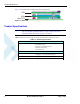
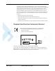
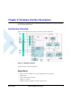
Figure 2-1 below illustrates the primary functional components of the W24.
Figure 2-1: W24 Block Diagram
The W24 consists of the following blocks:
Digital Block
• Micro-controller Unit (MCU) for system and application code execution.
• 1MByte Flash.
• Serial communications interfaces.
• USB Device interface.
• USB Host interface (available on cellular connector only).