
Wi-Fi Module Developer's Guide


A/D Converter Interface
26 Module Hardware Description May 31, 2008
A/D Converter Interface
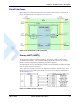
W24 incorporates Analog to Digital Converter interface intended to support G24 ADC interface,
in stacked configuration. The interface consists of the following pins (see Table 2-10):
The above signals are routed from 70-pin host connector to G24 70-pin connector via W24. They
are not internally connected to W24 circuits. If the W24 will be used as stand alone only, the
above pins should be left open.
For more details on implementing a ADC interface for use with G24, please refer to the
"Motorola G24 Developer's Guide - Module Hardware Description" PN 6889192V27
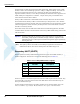
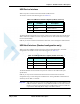
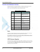
Table 2-10: ADC Interface Signals
Pin # Pin Name Description
37 ADC1 General purpose A/D
43 ADC2 General purpose A/D
47 ADC3 General purpose A/D