
Wi-Fi Module Developer's Guide


Chapter 2: Hardware Interface Description
May 31, 2008 Module Hardware Description 31
General Purpose I/O
W24 incorporates 8 General Purpose I/O interface. The interface consists of the following pins
(see Table 2-14):
In Stand alone configuration, GPIO pins 1 to 3 act as general purpose inputs.
GPIO pins 4 to 7 function as Bluetooth coexistence control/indicators for the W24 to use with a
Bluetooth interface in order to avoid RF collision between Bluetooth and Wi-Fi transmission.
There are 2, 3 or 4-wires coexistence configurations possible. Below is the functionality
description of relevant signals:
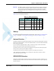
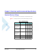
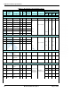
Table 2-14: GPIO Interface Signals
Pin # Pin Name Description
28 GPIO1 General purpose I/O
30 GPIO2 General purpose I/O
32 GPIO3 General purpose I/O
34 GPIO4 / BT_PRIORITY General purpose I/O / Bluetooth
coexistence indication
36 GPIO5 / BT_FREQ General purpose I/O, Bluetooth
coexistence indication
38 GPIO6 / BT_STATE General purpose I/O, Bluetooth
coexistence indication
40 GPIO7 / WL_ACTIVE General purpose I/O, Bluetooth
coexistence indication
42 GPIO8 General purpose I/O
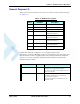
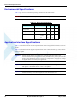
Pin Name Direction Description
GPIO4 / BT_PRIORITY I In 2-Wires coexistence: When High, BT is trans-
mitting or receiving high priority packets.
In 3-Wires coexistence: When High, BT PA is on or
BT is receiving data.
GPIO5 / BT_FREQ I This pin is not used for 2-wire and 3-wire Bluetooth
coexistence scheme. This pin can be used for
4-wire interface if needed.
This pin should either be left floating or be con-
nected to ground.