
Wi-Fi Module Developer's Guide


Application Interface Specifications
42 Module Hardware Description May 31, 2008
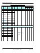
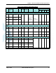
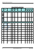
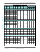
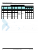
Table 3-4: G24 Interface Specifications
Pin #
Signal
Name
Description I/O
Active
H/L
Internal
PU/PD
Parameter Conditions
Level
Min Typ Max Units
Power:
1
GND Ground
2
3
4
5
VCC DC power O
V
IN
I
MAX
I
OFF
VCC = 3.6 V
3.3 3.6 4.2 V
6 220 490 mA
7 10 100 µA
8
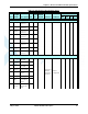
Control:
27 G24_VRE
F
Reference
regulator out-
put
NC N/A
16 G24_WK
UPI_N
W24 wakeup
input
O L 15K PU V
IH
V
IL
2
0
3.15
0.8
V
26 G24_WK
UPO_N
Host wakeup
output
I L 15K PU V
OH
V
OL
I
OUT
< 8 mA 2.75
0.4
V
25 G24_RES
ET_N
Reset signal
output
I L 15K PU V
OH
V
OL
I
OUT
< 8 mA 2.75
0.4
V
53 G24_ON_
N
On/Off switch O L 15K PU V
OH
V
OL
2.75
0.4
V
51 G24_IGN Ignition input O H 15K PU V
IH
V
IL
2
0.4
V
39 TXEN_N Transmit indi-
cator
I L 15K PU V
OH
V
OL
I
OUT
< 8 mA 2.75
0.4
V
41 G24_ANT
_DET
Antenna pres-
ence indicator
I H 15K PU V
OH
V
OL
I
OUT
< 8 mA 2.75
0.4
V
49 GPRS GPRS/
EGPRS cov-
erage indica-
tor
I L 15K PU V
OH
V
OL
I
OUT
< 8 mA 2.75
0.4
V