User Guide Wireless Ethernet Bridge WE800G
WARNING: TO PREVENT FIRE OR SHOCK HAZARD, DO NOT EXPOSE THIS PRODUCT TO RAIN OR MOISTURE. THE UNIT MUST NOT BE EXPOSED TO DRIPPING OR SPLASHING. DO NOT PLACE OBJECTS FILLED WITH LIQUIDS, SUCH AS VASES, ON THE UNIT. CAUTION: TO ENSURE REGULATORY COMPLIANCE, USE ONLY THE PROVIDED POWER AND INTERFACE CABLES. CAUTION: DO NOT OPEN THE UNIT. DO NOT PERFORM ANY SERVICING OTHER THAN THAT CONTAINED IN THE INSTALLATION AND TROUBLESHOOTING INSTRUCTIONS. REFER ALL SERVICING TO QUALIFIED SERVICE PERSONNEL.
Canadian Compliance This Class B digital apparatus meets all requirements of the Canadian Interference Causing Equipment Regulations. Cet appareil numérique de la classe B respects toutes les exigences du Règlement sur le matériel brouilleur du Canada. FCC Declaration of Conformity Motorola, Inc.
Contents Section 1:Overview _______________________ 1-1 Features ................................................................................................................ 1-2 Understanding your User Guide ......................................................................... 1-2 Box Contents ........................................................................................................ 1-3 Understanding Functions ............................................................................
CONTENTS Section 3:Configuration ___________________ 3-1 Using the Web-Based Configuration Utility ........................................................3-1 Logging In ...........................................................................................................3-1 Navigation ...........................................................................................................3-2 Help, Restart, and Log Out .................................................................................
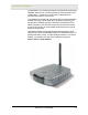
Section 1:Overview Congratulations on purchasing the Motorola Wireless Ethernet Bridge WE800G. With this unit, you have entered the world of freedom and independence – freedom from wires and the independence to communicate wherever YOU choose. The WE800G is built with both the popular 802.11b wireless standard and the new nearly 5-times-faster 802.11g standard, providing you the ultimate in flexibility and speed.
SECTION 1 OVERVIEW Features The WE800G has the following features: ! Wirelessly connects separate wireless networks together ! Connect any Ethernet equipped device to your wireless network; for example, a gaming console, a laptop or desktop computer, or a printer ! Compatibility with both 802.11g and 802.
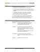
OVERVIEW SECTION 1 Box Contents Your box contains the following: Antenna Ethernet Cable CD-ROM Base Station Stand WE800G Power Adapter Power Cord Quick Start Guide Understanding Functions The various technologies and features used by your Wireless Ethernet Bridge require some conceptual explanation so that you can make the correct choices when configuring your unit.
SECTION 1 OVERVIEW TCP/IP Transmission Control Protocol/Internet Protocol (TCP/IP) comprises the backbone of the Internet. IP moves packets of data between nodes while TCP verifies delivery from client to server. Every device you hook up to your wireless router identifies itself with an IP address. You are able to assign devices on your network with either a static or dynamically assigned IP address.
OVERVIEW SECTION 1 Wireless Range The following describes different scenarios for the expected range of the coverage area of the unit. This table is only a guide and coverage varies due to local conditions. Data Rate Open Area Closed Area 54 Mbps Up to 100 ft (30m) Up to 60 ft (18m) 11 Mbps Up to 900 feet (275 m) Up to 160 feet (49 m) 5.
SECTION 1 OVERVIEW Type of Networks Your Wireless Ethernet Bridge supports several different usage scenarios and the following examples illustrate the flexibility of your WE800G. Some scenarios require additional hardware. Wireless Ethernet Bridge Infrastructure Mode In this mode, the WE800G functions like a bridge, connecting wired Ethernet clients to a wireless network. This is the most likely scenario you will use, because it shares an Internet connection with your laptop or other wireless client.
OVERVIEW SECTION 1 Wireless Ethernet Bridge Ad-Hoc Mode This mode is very similar to the Wireless Ethernet Bridge Infrastructure mode, except the WE800G will connect to other client devices using Ad-Hoc mode. One inherent limitation of operating in this mode is that all client devices must be in wireless range of each other, as opposed to a network with an Access Point, where all wireless devices must be in range of the Access Point.
SECTION 1 OVERVIEW Multiple Clients Mode In this mode, the WE800G connects multiple clients to your network wirelessly.
OVERVIEW SECTION 1 Wireless Ethernet Bridge Physical Description The following sections describe the physical characteristics of the WE800G. Back of Wireless Ethernet Bridge The following illustration shows the WE800G back panel: - + Reset Power LAN Power Receptacle LAN Port Antenna Reset Button Antenna Feature Description Power Receptacle The receptacle used to plug in the power adapter. LAN Port The receptacle used to plug in an Ethernet cable.
SECTION 1 OVERVIEW Feature Description Reset Button A dual-function button. It either resets your unit or resets the unit to the default login settings. If the Wireless Ethernet Bridge is experiencing trouble connecting to the Internet, briefly press and release the Reset button to reset the router. This retains the router’s configuration information. To reset the unit to the factory defaults while the unit is powered up, press and hold the Reset button for more than five seconds.
OVERVIEW SECTION 1 Front of Wireless Ethernet Bridge The following illustration shows the WE800G front panel: r we Po s les ire W 1. 2. e vic De 3. The LEDs of the unit indicate its operational status.
SECTION 1 OVERVIEW LED Description The underlined items represent network activity. LED 1. Power Condition Color Status ON Green The device is powered on and operating normally. Blinking Green Firmware update is in progress. Blinking/ON Red The power LED turns red as soon as the reset button is depressed.
Section 2:Installation To get your network up and running: 1 Setup your hardware. CAUTION! Use only the Motorola supplied WE800G power adapter. 2 Insert the CD-ROM for Software Setup. Follow the prompts. If you prefer to setup the Wireless Ethernet Bridge software manually, refer to the Manual Software Setup found in this section. The following sections provide detailed instructions for completing these tasks.
SECTION 2 INSTALLATION Wireless Ethernet Bridge Physical Installation You can install the Wireless Ethernet Bridge in different physical orientations – horizontally, vertically, or hung on the wall. Your own needs determine the best placement. Horizontal Installation To install the Wireless Ethernet Bridge horizontally, as shown in the illustration below: 2-2 1 Place the Wireless Ethernet Bridge in the desired location.
INSTALLATION SECTION 2 Vertical Installation To install the Wireless Ethernet Bridge vertically, as shown in the illustration below: 1 Insert the Wireless Ethernet Bridge into the supplied base. Ensure that the antenna’s location is on top, because the antenna prevents the unit from fitting into the base. The Wireless Ethernet Bridge’s foot slides snugly into the base to keep the unit stable.
SECTION 2 INSTALLATION If possible, mount the Wireless Ethernet Bridge to concrete, masonry, a wooden stud, or other solid wall material. Use anchors if necessary; for example if you must mount the unit on drywall. Mounting the unit on the wall may decrease performance. To mount your Wireless Ethernet Bridge on the wall: 1 Print the Wall Mounting Template. 3.15 [80.
INSTALLATION SECTION 2 3 Click OK to print the template. 4 Measure the printed template with a ruler to ensure that it is the correct size. 5 Use a center punch to mark the center of the holes on the wall. 6 On the wall, locate the marks for the mounting holes you just made. WARNING! Before drilling holes, check the structure for potential damage to water, gas, or electric lines. 7 Drill the holes to a depth of at least 3.8 cm (1½ inches). 8 If necessary, seat an anchor in each hole.
SECTION 2 INSTALLATION Electrical Connection to Wireless Ethernet Bridge Your Wireless Ethernet Bridge does not have an On/Off power switch and will only be powered on by plugging in the power adapter. To make the electrical connection to the Wireless Ethernet Bridge: CAUTION! Use only the Motorola supplied WE800G power adapter.
INSTALLATION SECTION 2 Easy Software Setup Run the Installation Wizard program from the supplied CD-ROM to quickly setup your network. Once your network is up and running, refer to Section 3:Configuration for advanced configuration. Manual Software Setup If you’d prefer to manually setup your network, use this section to configure it. This section describes the physical connection of the Wireless Ethernet Bridge to your network as well as the configuration needed by your PC.
SECTION 2 INSTALLATION Wired Connection to Wireless Ethernet Bridge This section applies if you are connecting your PC with an Ethernet cable to the Wireless Ethernet Bridge. Your PC must be installed first with an Ethernet adapter. You need the supplied Ethernet cable to connect the PC to the Wireless Ethernet Bridge.
INSTALLATION SECTION 2 Configure Your Computers For initial configuration, you need to initially configure the PC’s network setting to specify a static IP address for the computer that is going to “talk” to the Ethernet Bridge. After initial configuration: If using DHCP Reconfigure the PC’s settings to Obtain an IP address automatically. If not using DHCP Continue to use the Static IP settings.
SECTION 2 INSTALLATION Configuring Windows 98SE and ME 1 Click Start. 2 Select Settings > Control Panel. 3 Double-click Network. The Network window is displayed: 4 On the configuration tab, select the TCP/IP line the for the appropriate Ethernet adapter. There might be multiple adapters installed – choose only the one that is configured for your adapter. In the example above, a 3Com Ethernet adapter card is installed and is the appropriate choice for this example.
INSTALLATION SECTION 2 5 Click Properties. The TCP/IP Properties window is displayed: 6 Click the IP address tab. 7 Enter 192.168.30.1 into the IP Address field. 8 Enter 255.255.255.0 into the Subnet Mask field. 9 Click OK. 10 Click the Gateway tab and check to make sure that the Installed Gateway field is blank. 11 Click OK twice. Windows might ask for the Windows installation disk. First check to see if the installation files are installed at c:\windows\options\cabs.
SECTION 2 INSTALLATION Windows 98 and ME DHCP Server Configuration After your initial configuration has been completed, you may need to setup your PC for using a DHCP server, using the procedure below. 1 Follow Steps 1 through 6 from above. Windows 98SE Windows ME 2 Select Obtain an IP address automatically. 3 Click OK and then complete the procedure by following steps 10 through 12. Configuring Windows 2000 2-12 1 Click Start. 2 Select Settings. 3 Select Control Panel.
INSTALLATION SECTION 2 5 Double-click Local Area Connection. 6 Click the Properties button. 7 Ensure the box next to Internet Protocol (TCP/IP) is selected.
SECTION 2 INSTALLATION 8 Click to highlight Internet Protocol (TCP/IP) and click the Properties button. 9 Enter 192.168.30.10 into the IP Address field. 10 Enter 255.255.255.0 into the Subnet Mask field. 11 Click OK twice to exit and save your settings. 12 Restart your computer to save your settings. 13 Proceed to the Configure Your Wireless Settings section to set up the security settings.
INSTALLATION SECTION 2 Windows 2000 DHCP Server Configuration After your initial configuration has been completed, you may need to setup your PC for using a DHCP server, using the procedure below. 1 Follow Steps 1 through 8 from above. 2 Select Obtain an IP address automatically. 3 Click OK and then complete the procedure by following steps 11 and 12. Configuring Windows XP This configuration assumes you have retained the default interface for Windows XP.
SECTION 2 2-16 INSTALLATION 5 Double-click Local Area Connection. The Local Area Connection Status window appears. 6 Click the Properties button. 7 Ensure the box next to Internet Protocol (TCP/IP) is selected.
INSTALLATION SECTION 2 8 Click to highlight Internet Protocol (TCP/IP) and click the Properties button. 9 Enter 192.168.30.10 into the IP Address field. 10 Enter 255.255.255.0 into the Subnet Mask field. 11 Click OK twice to exit and save your settings. 12 Proceed to the Configure Your Wireless Settings section to set up the security settings.
SECTION 2 INSTALLATION Windows XP DHCP Server Configuration After your initial configuration has been completed, you may need to setup your PC for using a DHCP server, using the procedure below. 2-18 1 Follow Steps 1 through 8 from above. 2 Select Obtain an IP address automatically. 3 Click OK and then complete the procedure by following step 11.
INSTALLATION SECTION 2 Configure Your Wireless Security Settings Due to the limitation of the Wi-Fi WPA Test Plan, your Wireless Ethernet Bridge’s factory default settings are not set at their maximum security level. Adjustments are strongly recommended to ensure that you communicate securely on your wireless network at maximum strength. Failure to configure these settings properly could compromise your network to wireless hackers.
SECTION 2 INSTALLATION After you have logged in, for security reasons, you should change the User ID and Password. See Wireless Security Setup. 4 Click the LOG IN button to enter the Wireless Ethernet Bridge’s Web-based Configuration Utility. Wireless Security Setup Follow these procedures to setup the correct security protocols for your Wireless Ethernet Bridge. 1 Select Control Panel > Device Security. 2 In the Login User ID field, enter in the desired USER ID.
Section 3:Configuration You can use the information in this section to modify the Wireless Ethernet Bridge’s settings. For example you can customize features for your home network, change settings such as your user name or password, view the status of the network, and more. Using the Web-Based Configuration Utility Logging In 1 After the Wireless Ethernet Bridge is connected, open your web browser. Enter into the URL field the Wireless Ethernet Bridge’s IP address. The default is http://192.168.30.
SECTION 3 CONFIGURATION Navigation Each of the following subsections provides descriptions for the components of the Wireless Ethernet Bridge’s Configuration Utility – accessible from a web browser. These sections include: ! Site Survey ! Wireless Profile 1 ! Wireless Profile 2 ! Control Panel To navigate, click on a major section and then the associated subsection. For example, to set the security profile for Profile 1, click WIRELESS PROFILE 1 on the left, then the BASIC tab at top on the right.
CONFIGURATION SECTION 3 Active Profile and Site Monitor These screens enable you to configure your Wireless Ethernet Bridge for different wireless scenarios and to search for Access Points (APs). ! Active Profile ! Site Monitor Site Survey – Active Profile This is the first screen that appears when logging into the web-based utility. It enables you to select the Profile you want to use. A Profile enables you to configure your unit for different wireless networks.
SECTION 3 CONFIGURATION Site Survey – Site Monitor This screen displays information about wireless Access Points (AP) and stations, and their associated information. The settings displayed here help you to configure the Ethernet Bridge appropriately. To access the screen, click Site Survey > Site Monitor. Click APPLY to save your settings or CANCEL to cancel changes. 3-4 Field or Button Description Scan Click to search for more access points/routers.
CONFIGURATION SECTION 3 Configuring Wireless Profile 1 or 2 The Wireless Profile 1 or 2 screens enable you to adjust settings for your wireless connection for a specific wireless profile. Refer to each subsection for further descriptions. These include: ! Basic ! Security ! Advanced ! Professional Wireless – Basic This screen enables you to setup your Service Set Identifier (SSID) parameters for your network.
SECTION 3 CONFIGURATION Wireless – Security This screen enables wireless security settings. Some fields activate other options. Refer to the descriptions for details. To access the screen, click Wireless Profile 1 or 2 > Security. Click APPLY to save your settings or CANCEL to cancel changes. Field Description SSID Broadcast Service Set Identifier (SSID). Broadcasts the SSID of the Wireless Ethernet Bridge to devices on your network. This option is only available when Ad-Hoc is enabled.
CONFIGURATION SECTION 3 Field Description ESS Auth Mode Extended Service Set (ESS) Authentication Mode. Authentication differs from Encryption in that you are establishing either an open or secure verification of communication with an AP. This setting does not encrypt your transmission. The options are: Open System The Open System Authentication method is used, meaning the AP you are trying to associate with will not verify the identification of your unit.
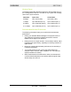
SECTION 3 CONFIGURATION Field Description Passphrase Enter the Passphrase to be used for Key encryption. This is the Passphrase used by other Access Points (AP), so you must enter the same phrase for all of the Motorola client devices on your wireless LAN. The Passphrase must be between 8 and 63 characters. Passphrase Confirmation Enter the Passphrase again. Key Input Method Available if Shared Key in ESS Auth Mode is selected.
CONFIGURATION SECTION 3 Field Description Key Index There are up to different 4 Keys (1, 2, 3, or 4) that can be selected, the amount determined by what is selected in the ESS Auth Mode or Encryption Status fields. You are selecting one of the Key Content fields below. The Key selected here must match between the WE800G and the AP in Infrastructure mode and other clients in Ad-Hoc mode. For example, if you select Key 1 here you have to match Key 1 of the AP.
SECTION 3 CONFIGURATION Wireless – Advanced This section enables you to turn on and off your wireless network and adjust wireless parameters. Generally, the settings here should remain at their default values. To access screen, click Wireless Profile 1 or 2 > Advanced. Click APPLY to save your settings or CANCEL to cancel changes. 3-10 Field Description Radio Interface Enables you to turn on and off the wireless feature. The default is enabled. MAC Address Displays the MAC address of the unit.
CONFIGURATION SECTION 3 Wireless – Professional This section enables you to turn on and off your wireless network and adjust wireless parameters. Generally, the settings here should remain at their default values. To access screen, click Wireless Profile 1 or 2 > Professional. Click APPLY to save your settings or CANCEL to cancel changes.
SECTION 3 CONFIGURATION Field Description Basic Rate Set The Wireless Ethernet Bridge broadcasts different transmission rates so clients know which transmission rate to use to join the network. The Mode selected on the Site Survey > Active Profile tab determines this setting. You can also alter the setting here. The default is Default. The options are: 11g Protection Mode All Ensures compatibility with all devices. Default Ensures compatibility with 802.11b or 802.
CONFIGURATION SECTION 3 Configuring Control Panel Settings The Control Panel screens enable administrative maintenance for your Wireless Ethernet Bridge, such as changing your User Name/Password, updating your firmware, or backing up your configuration.
SECTION 3 CONFIGURATION Field Description Connection Mode Select a connection mode. The options are DHCP or Static Assigned. Connection Status Provides current information about the connection status of the Wireless Ethernet Bridge. IP Address This is the IP address you use to connect to the unit. If connecting to a DHCP server, the IP address will appear here. If using Static Assignment, enter the IP address here. Subnet Mask This is the Subnet Mask address you use to connect to the unit.
CONFIGURATION SECTION 3 Field Description Login User ID Changes the User ID used for logging into the Wireless Ethernet Bridge’s web-based utility. It cannot be longer than 63 bytes. A blank user name is not allowed. The default is “admin”. Login Password Use this option to change the Password, used to log into the Wireless Ethernet Bridge’s web based utility. It cannot be longer than 63 bytes. A blank password is not allowed. The default is “motorola”.
SECTION 3 CONFIGURATION 3 Click Control Panel > Firmware Update. 4 Locate the file you downloaded, by typing the path to the file or clicking Browse and navigating to it. 5 Click UPDATE to update the Wireless Ethernet Bridge with the selected firmware file. 6 The Wireless Ethernet Bridge will inform you that you successfully updated the unit. 7 Follow the prompts for restarting.
Section 4:Troubleshooting This section details possible solutions to problems that might occur when using the Wireless Ethernet Bridge WE800G. Contact Us If you are unable to locate a solution here, please access our website at www.motorola.com/broadband/networking for the latest information. You can also reach us 7 days a week, 24 hours a day at 1-877-466-8646. Hardware Solutions My computer is experiencing difficulty connecting to the wireless network.
SECTION 4 TROUBLESHOOTING ! Ensure that you are using Ethernet cables and not telephone cables between the WE800G and your computer. Ethernet cables use a wider RJ-45 style plug using 8 wires where telephone style plugs use the smaller RJ-11 style plug using 4 to 6 wires. The plug on the left is RJ-45; the plug on the right is RJ-11 – use only RJ-45. ! Check the System Tray at the bottom right of your display to see You can click on this to an icon that looks like a monitor.
TROUBLESHOOTING SECTION 4 Software Solutions I cannot access the Configuration Utility for the unit. ! Verify your Ethernet connection to the WE800G. ! Verify that you are using the correct version of Internet Explorer or Netscape (Internet Explorer must be above version 5.2). ! Verify that the IP address of the PC being used to configure the router is on the same network as the router’s configuration IP address. The default IP address of WE800G is 192.168.30.1.
SECTION 4 TROUBLESHOOTING My WE800G cannot associate with the wireless access point/router. ! Ensure that your WE800G and the wireless access point/wireless router have the same security settings that enable your computer to access the wireless network. Section 2: Configure Your Wireless Security Settings describes how to adjust security settings.
TROUBLESHOOTING 2 SECTION 4 In the Command window, type ipconfig. ! You should see an IP address for your network adapter: Ethernet Adapter Local Area Connection: Connectionspecific DNS Suffix.: Example.example.example.com. IP Address. . . . . . . . . . . . : 192.168.30.2 Subnet Mask . . . . . . . . . . . : 255.255.255.0 Default Gateway . . . . . . . . . : 192.168.30.1 3 If using a router at home, in the Command window, type ping followed by the Router’s IP address and press Enter.
Section 5:Glossary A Access Point (AP) A device that provides wireless LAN connectivity to wireless clients (stations). Adapter A device or card that connects a computer, printer, or other peripheral device to the network or to some other device. A wireless adapter connects a computer to the wireless LAN. Address Translation See NAT. Ad-Hoc Network A temporary local area network connecting AP clients together, usually just for the duration of the communication session.
SECTION 5 GLOSSARY C Client In a client/server architecture, a client is a computer that requests files or services such as file transfer, remote login, or printing from the server. On an IEEE 802.11b/g wireless LAN, a client is any host that can communicate with the access point. Also called a CPE. A wireless client is also called a “station.” Also see server. Coaxial Cable A type of cable consisting of a center wire surrounded by insulation and a grounded shield of braided wire.
GLOSSARY SECTION 5 DNS The Domain Name System is the Internet system for converting domain names (like www.motorola.com) to IP addresses. A DNS server contains a table matching domain names such as Internetname.com to IP addresses such as 192.169.9.1. When you access the world-wide web, a DNS server translates the URL displayed on the browser to the destination website IP address. The DNS lookup table is a distributed Internet database; no one DNS server lists all domain name to IP address matches.
SECTION 5 GLOSSARY Ethernet The most widely used LAN type, also known as IEEE 802.3. The most common Ethernet networks are 10Base-T, which provide transmission speeds up to 10 Mbps, usually over unshielded, twisted-pair wire terminated with RJ-45 connectors. Fast Ethernet (100Base-T) provides speeds up to 100 Mbps. “Base” means “baseband technology” and “T” means “twisted pair cable.”’ Each Ethernet port has a physical address called the MAC address. Also see MAC address.
GLOSSARY SECTION 5 Host In IP, a host is any computer supporting end-user applications or services with full two-way network access. Each host has a unique host number that combined with the network number forms its IP address.
SECTION 5 GLOSSARY ISP Internet Service Provider L LAN Local Area Network. A local area network provides a full-time, high-bandwidth connection over a limited area such as a home, building, or campus. Ethernet is the most widely used LAN standard. M MAC Address The Media Access Control address is a unique, 48-bit value permanently saved in the ROM at the factory to identify each Ethernet network device. It is expressed as a sequence of 12 hexadecimal digits printed on the unit’s label.
GLOSSARY SECTION 5 Network Two or more computers connected to communicate with each other. Networks have traditionally been connected using some kind of wiring. NIC A Network Interface Card converts computer data to serial data in a packet format that it sends over the LAN. A NIC is installed in an expansion slot or can be built-in. Every Ethernet NIC has a MAC address permanently saved in its ROM.
SECTION 5 GLOSSARY Private IP Address An IP address assigned to a computer on the LAN by the DHCP server for a specified lease time. Private IP addresses are invisible to devices on the Internet. See also Public IP Address. Protocol A formal set of rules and conventions for exchanging data. Different computer types (for example PC, UNIX, or mainframe) can communicate if they support common protocols. Public IP Address The IP address assigned to a device by the service provider.
GLOSSARY SECTION 5 S Server In a client/server architecture, a dedicated computer that supplies files or services such as file transfer, remote login, or printing to clients. Also see client. Service Provider A company providing Internet connection services to subscribers. SMTP Simple Mail Transfer Protocol is a standard Internet protocol for transferring e-mail. Static IP Address An IP address that is permanently assigned to a host. Normally, a static IP address must be assigned manually.
SECTION 5 GLOSSARY TCP/IP The Transmission Control Protocol/Internet Protocol suite provides standards and rules for data communication between networks on the Internet. It is the worldwide Internetworking standard and the basic communications protocol of the Internet. Tunnel To place packets inside other packets to send over a network. The protocol of the enclosing packet is understood by each endpoint, or tunnel interface, where the packet enters and exits the network.
GLOSSARY SECTION 5 V VoIP Voice over Internet Protocol is a method to exchange voice, fax, and other information over the Internet. Voice and fax have traditionally been carried over traditional telephone lines of the PSTN (Public Switched Telephone Network) using a dedicated circuit for each line. VoIP enables calls to travel as discrete data packets on shared lines. VoIP is an important part of the convergence of computers, telephones, and television into a single integrated information network.
SECTION 5 GLOSSARY WPA Wi-Fi Protected Access. A security regimen developed by IEEE for protection of data on a WLAN. WWW World Wide Web. An interface to the Internet that you use to navigate and hyperlink to information.
Visit our website at: www.motorola.