Foreword This manual covers the ASTRO® XTL™1500 digital mobile radio with control head. It includes all the information necessary to maintain peak product performance and maximum working time, using levels 1 and 2 maintenance procedures. This level of service goes down to the board replacement level and is typical of some local service centers, self-maintained customers, and distributors. For details on radio operation or component-level troubleshooting, refer to the applicable manuals available separately.
Installation Requirements for Compliance with Radio Frequency (RF) Energy Exposure Safety Standards ATTENTION! This radio is intended for use in occupational/controlled conditions, where users have full knowledge of their exposure and can exercise control over their exposure to meet FCC limits. This radio device is NOT authorized for general population, consumer, or any other use.
This Page Intentionally Left Blank iv
Table of Contents v Table of Contents Foreword .........................................................................................................ii Product Safety and RF Exposure Compliance ............................................................................................ii Manual Revisions ........................................................................................................................................ii Parts Ordering ...............................................
vi Table of Contents 2.7 2.6.2 Handheld Hang-Up Box.................................................................................................. 2-11 Completing the Installation .......................................................................................................... 2-11 Chapter 3 3.1 3.2 3.3 Options and Accessories Installation ............................... 3-1 VIP Overview .....................................................................................................
Table of Contents vii Related Publications ASTRO XTL 1500 User’s Guide ................................................................................................. 6815850H01 ASTRO XTL 1500 CD (User’s Guide & Installation Manual)....................................................... 6815852H01 ASTRO XTL 1500 Basic Service Manual.................................................................................... 6815853H01 ASTRO XTL 1500 Detailed Service Manual .......................................
viii List of Figures List of Figures Figure 1-1. Front View of Dash Mount Brick Trunnion ............................................................................ 1-1 Figure 1-2. Side View of Dash Mount Brick Trunnion ............................................................................. 1-1 Figure 1-3. Dash Mount Configuration .................................................................................................... 1-2 Figure 2-1. Mounting Flexibility in Middle Console...............
List of Tables ix List of Tables Table 3-1. Table 3-2. Table 3-3. Table 3-4. 6815851H01-O VIP Output Connections .............................................................................................3-1 Rear Accessory Jack Pin Functions .........................................................................3-10 Rear Connector and Front Connector Naming Schemes ......................................... 3-11 How to Connect to a Computer1 (DTE Device) ..............................................
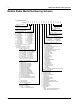
x Mobile Radio Model Numbering Scheme Mobile Radio Model Numbering Scheme Typical Model Number: M Position: 1 2 2 0 3 U 4 R 5 Position 1 -Type of Unit M = Mobile L = Table Top Station Positions 2 & 3 - Model Series 20 = XTL 1500 Position 4 - Frequency Band = Less than 29.7MHz N = 330 to 370MHz = 29.7 to 35.
Commercial Warranty xi Commercial Warranty Limited Warranty MOTOROLA COMMUNICATION PRODUCTS I. What This Warranty Covers And For How Long MOTOROLA INC.
xii Commercial Warranty III. State Law Rights SOME STATES DO NOT ALLOW THE EXCLUSION OR LIMITATION OF INCIDENTAL OR CONSEQUENTIAL DAMAGES OR LIMITATION ON HOW LONG AN IMPLIED WARRANTY LASTS, SO THE ABOVE LIMITATION OR EXCLUSIONS MAY NOT APPLY. This warranty gives specific legal rights, and there may be other rights which may vary from state to state. IV.
Commercial Warranty xiii VI. Patent And Software Provisions MOTOROLA will defend, at its own expense, any suit brought against the end user purchaser to the extent that it is based on a claim that the Product or parts infringe a United States patent, and MOTOROLA will pay those costs and damages finally awarded against the end user purchaser in any such suit which are attributable to any such claim, but such defense and payments are conditioned on the following: A.
xiv Commercial Warranty Notes June 2, 2005 6815851H01-O
Chapter 1 Introduction This manual covers the installation procedures for ASTRO XTL 1500 mobile and accessories required to complete the radio system. The radio system consists of a control head, radio, antenna, microphone, cabling, and accessories. 1.1 Mobile Radio Description 1.1.1 Dimensions Figure 1-1 and Figure 1-2 show the basic dimensions of the dash mount brick trunnion XTL 1500 radio.
1-2 Introduction: Standard Configurations 1.2 Standard Configurations 1.2.1 Dash Mount Configuration The control head is mounted on the front of the transceiver housing. Electrical connection between the two takes place within the radio via a flexible circuit board between the connectors on the front of the transceiver and at the back of the control head. Figure 1-3. Dash Mount Configuration For details on this configuration, see Section 2.2.1 on page 2-5. 1.
Introduction: Tools Required for XTL 1500 Installations 1.
1-4 Introduction This Page Intentionally Left Blank June 3, 2005 6815851H01-O
Chapter 2 Standard Configurations 2.1 Planning the Installation The XTL 1500 radio operates only in negative ground electrical systems. Before starting the radio installation, make sure that the ground polarity of the vehicle is correct. Accidentally reversing the polarity will not damage the radio, but will cause the cable fuses to blow. Planning is the key to fast, easy radio installation.
2-2 2.1.1 Standard Configurations: Planning the Installation Installation Examples Your mobile two-way radio offers only dash mount installation. (see Figure 2-1 through Figure 2-3). Speaker (optional) Antenna 1/4-Wavelength Radio Antenna 1/4-Wavelength Radio Battery Radio Battery Figure 2-1. Mounting Flexibility in Middle Console Speaker (optional) Speaker (optional) Figure 2-2. On Top or Under Dash Mounting Antenna 1/4-Wavelength Radio Battery Figure 2-3.
Standard Configurations: Planning the Installation 2.1.2 2-3 Wiring Diagrams Figure 2-4 shows the wiring diagram the possible configurations. The title under the figure identifies the control head configurations. Use the diagram when planning the installation.
2-4 2.2 Standard Configurations: Radio Mounting Radio Mounting ! Caution CAUTION: DO NOT mount the radio on a plastic dashboard without first reinforcing the dashboard; the weight of the radio may crack or break the dashboard. CAUTION: DO NOT mount the radio on a flat or concave surface where the radio could be partially submersed in water. This is especially important if the cab area of the vehicle is cleaned by spraying with water.
Standard Configurations: Radio Mounting 2.2.1 2-5 Dash Mount with Trunnion 1. Select the location to mount your radio on the transmission hump (see Figure 2-6) or under the dash (see Figure 2-7). When mounting the trunnion on the transmission hump take care the transmission housing is not affected. 2. Using the trunnion mounting bracket as a template, mark the positions of the holes on the mounting surface.
2-6 2.2.2 Standard Configurations: Power Cable and Ignition Locking Kit (Optional) If an optional locking kit is used (shown in Figure 2-8), position the lock bottom housing on the trunnion before installing the radio mounting screws. Then slip the top lock housing on and remove the key. You can install the lock on either side of the radio, and by rotating it 180°, you can also install it on dash installations. Existing Mounting Screw Lock Housing Lock Figure 2-8. Locking Kit (Optional) 2.
6815851H01-O CH SPEAKER (Optional) MICROPHONE Figure 2-9. Cabling Interconnect Diagram for Dash Mount SEE NOTE ON/ACC VEHICLE IGNITION SWITCH 3A OR 4A FUSE RADIO POWER CABLE (RED/BATTERY HOT) RADIO IGNITION CABLE (thin RED) Caution: Always wire the radio’s IGNITION line to the car’s ignition switch. Rear connector RADIO RADIO POWER CABLE (BLK/GROUND) A good chassis connection via the black primary power cable is essential for radio operation and to prevent damage to the radio and cable kit.
2-8 2.4 Standard Configurations: Ignition Sense Cable Ignition Sense Cable Motorola supplies an ignition sense cable and recommends that it be used with every mobile installation. The ignition sense cable allows the radio to be turned on and off with the vehicle ignition switch, and allows the radio to “remember” the state of the radio on/off switch, even if it is changed while the vehicle is off. Note that this feature can be turned on/off via Motorola CPS software.
Standard Configurations: Antenna Installation 2-9 4. Mounting restrictions for certain radio models For 40 Watt UHF models, the 1/4 wave antenna should be mounted only in the center area of the roof, not on the trunk lid, to assure compliance with RF Energy Safety standards. 5. Ensure that the antenna cable can be easily routed to the radio. Route the antenna cable as far away as possible from any vehicle electronic control units and associated wiring. 6.
2-10 Standard Configurations: Antenna Installation 1. Make sure that there is sufficient slack in the antenna cable. 2. Make sure that the collar of the antenna cable plug is loose and does not bind. 3. Make sure that the mini-UHF jack is tight in the radio housing. 4. Slide the collar back against the flange. Insert the antenna cable plug’s pin fully into the radio jack, but do not engage the threads. 5. Ensure that the plug’s and jack’s interlocking features are fully seated.
Standard Configurations: Microphone Hang-Up Clip 2.6 Microphone Hang-Up Clip 2.6.1 Standard Hang-Up Clip 2-11 The hang-up clip must be within reach of the operator(s). Measure this distance before actually mounting the bracket. Since the bracket has a positive-detent action, the microphone can be mounted in any position. The microphone hang-up clip must be grounded. Use the hang-up clip as a template to locate the mounting holes.
2-12 Standard Configurations: Completing the Installation This Page Intentionally Left Blank June 3, 2005 6815851H01-O
Chapter 3 Options and Accessories Installation 3.1 VIP Overview The vehicle interface port (VIP) allows the control head to operate outside circuits and to receive inputs from outside the control head. There are three VIP outputs which are used for relay control. There are also three VIP inputs which accept inputs from switches. 3.1.1 VIP Output Connections The VIP output pins are on the back or the rear of the accessory panel (J2). The pin information is shown in Figure 3-6.
3-2 3.1.2 Options and Accessories Installation: VIP Overview Emergency Pushbutton, Footswitch, Horn Relay, and Light Relay Installation ! Caution CAUTION: When connecting the various microphones available, make sure to attach the S-hook provided on the microphone cable (see Figure 2-7 in Chapter 2) to the dash or remote mount trunnion to avoid damage to the microphone control head interconnect. Perform the following installation procedure: 1.
Options and Accessories Installation: Dash-Mount Accessory Installation 3.2 3-3 Dash-Mount Accessory Installation For dash-mounted configurations, the accessories must be installed through the accessory connector assembly that is located on the rear of the radio, adjacent to the power connector. Motorola-approved accessories are supplied with male terminals crimped to a 20-gauge wire specifically designed to fit the plug of the accessory connector assembly.
3-4 Options and Accessories Installation: Dash-Mount Accessory Installation SPST N.O. RELAY CONNECT ACROSS HORN RING SWITCH VIP OUT 1 PIN 18 12V COIL SWB+ SPST N.O. RELAY CONNECT ACROSS HEAD LAMP SWITCH PIN 24 VIP OUT 2 PIN 19 ACCESSORIES CONNECTOR 12V COIL 7 20 13 26 VIP OUT 2 (LIGHTS) VIP OUT 1 (HORN) SWB+ 8 21 14 1 MAEPF-27618-O Figure 3-3. Horn/Light Wiring Diagram 3.2.3 External Speaker (HSN4031_) ! CAUTION: DO NOT use an external speaker which exceeds 7.5W or is below 8 Ohm.
Options and Accessories Installation: Accessory Connector Assembly Details (P2) Trunnion Bracket Dashboard Firewall 3-5 OR MAEPF-25764-O Figure 3-4. Speaker Mounting 3.3 Accessory Connector Assembly Details (P2) The XTL 1500 accessory connector assembly is mounted on the right rear of the radio, opposite the antenna and adjacent to the power connector. It is fastened to the radio via jackscrews and held together by the two cover screws.
3-6 3.3.1 Options and Accessories Installation: Accessory Connector Assembly Details (P2) Installation into the Vehicle CAUTION Before installing any electrical equipment, check the vehicle manufacturer’s user manual. The installation of this device should be completed by an authorized servicer or installer. 1. Disconnect the negative terminal from the vehicle’s battery. Make sure that the battery cable is secured such that it will not power the vehicle’s electrical system. 2.
Options and Accessories Installation: Accessory Connector Assembly Details (P2) 3.3.3 3-7 Disassembly and Assembly 3.3.3.1 Disassembly 1. Disconnect the negative terminal from the vehicle’s battery. Make sure that the battery cable is secured such that it will not power the vehicle’s electrical system. See Figure 3-5. 2. Unscrew both jackscrews completely. 3. Pull the accessory connector assembly out from the radio. 4. Loosen both cover screws, but do not remove them completely. 5.
3-8 Options and Accessories Installation: Accessory Connector Assembly Details (P2) 5. Squeeze the covers together bending the wires in the strain-relief features. You may need a pair of pliers to seat the assembly covers. 6. Once the covers are fully seated, fasten them with the cover screws. Tighten the screws firmly but do not over-tighten them. Be sure none of the wires are pinched. 7.
Options and Accessories Installation: Accessory Connector Assembly Details (P2) 3.3.4 3-9 Transceiver Rear Accessory Jack Connection Figure 3-6 shows the complete pin configuration for the J2 rear accessory jack and Table 3-2 explains the functions of each of the pins.
3-10 Options and Accessories Installation: Accessory Connector Assembly Details (P2) Table 3-2. Rear Accessory Jack Pin Functions Pin No. 1 2 3 4 5 Pin Name Pin Function Pin No.
Options and Accessories Installation: Accessory Connector Assembly Details (P2) 3-11 Table 3-3. Rear Connector and Front Connector Naming Schemes J2 Pin Name1 J2 Pin Number 1 2 Pin Alternate Name EIA Compatible Name at Rear Connector J22 J2-4 UARTA_TX No change TX_DCE J2-5 UARTA_RX No change RX_DCE J2-10 UARTA_CTS Becomes RTS RTS_DCE J2-11 UARTA_RTS Becomes CTS CTS_DCE As indicated for front and rear connectors Pin function as a true “DCE” device according to EIA standard Table 3-4.
3-12 Options and Accessories Installation: Accessory Connector Assembly Details (P2) This Page Intentionally Left Blank June 3, 2005 6815851H01-O
Chapter 4 Finishing the Installation: Cable Connection Perform the following if it has not been previously done: 1. The microphone can be plugged into the lower left corner of the control head front panel. Connect the microphone cable S-hook (see Figure 2-7 in Chapter 2) into the hole in the cable strain relief bracket on the mounting trunnion. 2. Be sure the control head is OFF.
4-2 Finishing the Installation: Cable Connection Notes June 3, 2005 6815851H01-O
Appendix A A.1 Replacement Parts Ordering Basic Ordering Information When ordering replacement parts or equipment information, the complete identification number should be included. This applies to all components, kits, and chassis. If the component part number is not known, the order should include the number of the chassis or kit of which it is a part, and sufficient description of the desired component to identify it.
A-2 A.4 Replacement Parts Ordering: Telephone Orders Telephone Orders Radio Products and Services Division* (United States and Canada) 7:00 AM to 7:00 PM (Central Standard Time) Monday through Friday (Chicago, U.S.A.) 1-800-422-4210 1-847-538-8023 (International Orders) U.S. Federal Government Markets Division (USFGMD) 1-800-826-1913 Federal Government Parts - Credit Cards Only 8:30 AM to 5:00 PM (Eastern Standard Time) A.
Glossary Glossary This glossary contains an alphabetical listing of terms and their definitions that are applicable to ASTRO portable and mobile subscriber radio products. Term Definition A/D See analog-to-digital conversion. Abacus IC A custom integrated circuit providing a digital receiver intermediate frequency (IF) backend. ADC See analog-to-digital converter. ADDAG See Analog-to-Digital, Digital-to-Analog and Glue. ALC See automatic level control.
Glossary-2 Term Definition BBP See baseband interface port. baseband interface port Synchronous serial interface to the transceiver board used to transfer transmit and receive audio data. BGA See ball grid array. ball grid array A type of IC package characterized by solder balls arranged in a grid that are located on the underside of the package. CODEC See coder/decoder. coder/decoder A device that encodes or decodes a signal. CPS See Customer Programming Software.
Glossary-3 Term Definition digital signal processor code Object code executed by the Digital Signal Processor in an ASTRO subscriber radio. The DSP is responsible for computation-intensive tasks, such as decoding ASTRO signaling. DPL See Digital Private-Line. See also PL. DSP See digital signal processor. DSP code See digital signal processor code. DTE Data terminal equipment: i.e., a computer. DTMF See dual tone multi-frequency.
Glossary-4 Term Definition frequency Number of times a complete electromagnetic-wave cycle occurs in a fixed unit of time (usually one second). frequency generation unit This unit generates ultra-stable, low-phase noise master clock and other derived synchronization clocks that are distributed throughout the communication network. General-Purpose Input/Output Pins whose function is programmable. GPIO See General-Purpose Input/Output.
Glossary-5 Term Definition LSH See low-speed handshake. Master In Slave Out SPI data line from a peripheral to the MCU. Master Out Slave In SPI data line from the MCU to a peripheral. MCU See microcontroller unit. MDC Motorola Digital Communications. MDI MCU/DSP Interface internal to the Patriot IC. MHz See Megahertz. Megahertz One million cycles per second. Used especially as a radio-frequency unit. microcontroller unit Also written as µC.
Glossary-6 Term Definition paging One-way communication that alerts the receiver to retrieve a message. Patriot IC A dual-core processor that contains an MCU and a DSP in one IC package. PC Board Printed Circuit Board. Also referred to as a PCB. phase-locked loop A circuit in which an oscillator is kept in phase with a reference, usually after passing through a frequency divider. PL See private-line tone squelch. PLL See phase-locked loop.
Glossary-7 Term Definition real-time clock A module that keeps track of elapsed time even when a computer is turned off. receiver Electronic device that amplifies RF signals. A receiver separates the audio signal from the RF carrier, amplifies it, and converts it back to the original sound waves. registers Short-term data-storage circuits within the microcontroller unit or programmable logic IC.
Glossary-8 Term Definition Serial Peripheral Interface How the microcontroller communicates to modules and ICs through the CLOCK and DATA lines. signal An electrically transmitted electromagnetic wave. Signal Qualifier mode An operating mode in which the radio is muted, but still continues to analyze receive data to determine RX signal type. softpot See software potentiometer. software Computer programs, procedures, rules, documentation, and data pertaining to the operation of a system.
Glossary-9 Term Definition transmitter Electronic equipment that generates and amplifies an RF carrier signal, modulates the signal, and then radiates it into space. TSOP See thin small-outline package. TX Transmit. UART See also Universal Asynchronous Receiver Transmitter. UHF Ultra-High Frequency. Universal Asynchronous Receiver Transmitter A microchip with programming that controls a computer's interface to its attached serial devices.
Glossary-10 Notes June 3, 2005 6815851H01-O
Index Index accessories installations ........................................ 3-3 configuration .......................................................... 1-2 installation .............................................................. 2-3 installation examples ............................................. 2-2 radio dimensions ................................................... 1-1 trunnion ................................................................. 2-5 A accessories connector assembly ............
Index-2 mounting, antenna restrictions ............................................................. 2-9 roof top .................................................................. 2-8 trunk lid .................................................................. 2-8 installation examples ............................................. 2-2 replacement parts, ordering ...................................... A-1 O speaker mounting ........................................................ 3-4, 3-5 pigtail .......