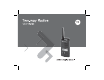
Motorola, the Stylized M Logo, and all other trademarks indicated as such herein are Trademarks of Motorola, Inc. Reg. U.S. Pat. & Tm. Off. © 2007 Motorola, Inc. All rights reserved. Printed in the U.S.A.
CONTENTS Battery Features and Charging Options . .12 About the Li-Ion Battery . . . . . . . . . . . .12 Battery Recycling and Disposal . . . . . .13 Computer Software Copyrights . . . . . . . 4 Installing the Lithium-Ion (Li-Ion) Battery . Safety . . . . . . . . . . . . . . . . . . . . . . . . . . . . 5 . . . . . . . . . . . . . . . . . . . . . . . . . . . . . .14 Product Safety and RF Exposure Compliance . . . . . . . . . . . . . . . . 5 Removing the Lithium-Ion (Li-Ion) Battery. . . . . . . . . . .
CONTENTS Charging a High Capacity Battery. . . . 22 Reset To Factory Defaults . . . . . . . . . .32 Drop-in Tray Charger LED Indicators . 23 End of Transmission Tone (Roger Beep Tone) . . . . . . . . . . . . . . . . . . . . . . . . . .33 Estimated Charging Time . . . . . . . . . . 24 Charging a Radio and Battery Using a MultiUnit Charger-MUC (Optional Accessory) Keypad Beeps . . . . . . . . . . . . . . . . . . .33 . . . . . . . . . . . . . . . . . . . . . . . . . . . . . . .
Carry Accessories . . . . . . . . . . . . . . . . . . .64 Editing Channel Alias Name . . . . . . . . . . 46 Software Applications . . . . . . . . . . . . . . . .64 Nuisance Channel Delete . . . . . . . . . . . . 47 Cables . . . . . . . . . . . . . . . . . . . . . . . . . . . .64 CPS (Computer Programming Software). 48 Chargers . . . . . . . . . . . . . . . . . . . . . . . . . .65 Bandwidth Select . . . . . . . . . . . . . . . . 48 Time-Out Timer . . . . . . . . . . . . . . . . . .
COMPUTER SOFTWARE COPYRIGHTS COMPUTER SOFTWARE COPYRIGHTS The Motorola products described in this manual may include copyrighted Motorola computer programs stored in semiconductor memories or other media. Laws in the United States and other countries preserve for Motorola certain exclusive rights for copyrighted computer programs, including, but not limited to, the exclusive right to copy or reproduce in any form the copyrighted computer program.
SAFETY PRODUCT SAFETY AND RF EXPOSURE COMPLIANCE ! Caution Before using this product, read the operating instructions and RF energy awareness information contained in the Product Safety and RF Exposure booklet enclosed with your radio. For a list of Motorola-approved antennas, batteries, and other accessories, visit the following website which lists approved accessories: http://www.motorola.
BATTERIES AND CHARGERS SAFETY INFORMATION BATTERIES AND CHARGERS SAFETY INFORMATION 4. An extension cord should not be used unless absolutely necessary. Use of an improper extension cord could result in risk of fire and This document contains important safety and operating instructions. Read these instructions carefully and save them for future reference. electric shock.
• Turn the radio OFF when charging battery. • The charger is not suitable for outdoor use. Use only in dry locations/conditions. • Connect charger only to an appropriately fused and wired supply of the correct voltage (as • Maximum ambient temperature around the power supply equipment must not exceed 40°C (104°F). • Make sure the cord is located where it will not be stepped on, tripped over, or subjected to water, damage, or stress. specified on the product).
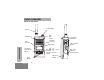
RADIO OVERVIEW PARTS OF THE RADIO LED Indicator Antenna ON/ OFF/ Volume Microphone Accessory Connector LED Indicator RADIO OVERVIEW Model Label Use ‘Menu’ button to lock keypad Use / to scroll up/down through channels and menu setting Lithium-Ion Battery Front Buttons English PTT (Push-toTalk) Button 8 SB1 - Monitor Button SB2 - Scan/ Nuisance Channel Delete
ON/OFF/Volume Knob Front Buttons Used to turn the radio ON or OFF and to adjust the radio’s volume. Microphone Speak clearly into the microphone when sending a message. Antenna The radio’s antenna is non-removable. Accessory Connector • M E NU Button Used to connect compatible audio LED Indicator • Used to give battery status, power-up status, radio call information and scan status. Allows you to scroll up/down the menu options or set up programming values.
• A Default set to generate the current programmed call tone. • (Computer Programming Software)” on Programmable Button B Programmable Button page 48. Side Buttons • Push-to-Talk (PTT) Button Default set to preset channel 1 Press and hold down this button to talk, release it to listen. • • C Programmable Button Default set to preset channel 2 Note: A short press of either preset button (B or C) tunes the radio to the preset channel and the radio will play a good chirp.
This User Guide covers multiple radio models, and may detail some features your radio does not have. The model number of the radio is shown on the front of the radio, underneath the speaker, and tells you the following information: Model Frequency Band Transmit Power (Watts) Number of Channels Antenna XTNiD PMR446 0.
BATTERIES AND CHARGERS BATTERIES AND CHARGERS XTNi™ Series radios provide Lithium-Ion (LiIon) batteries that comes in different capacities that will define the battery life. It also offers the option to use Alkaline batteries.The radio comes equipped with a rapid charger. BATTERY FEATURES AND CHARGING OPTIONS About the Li-Ion Battery The XTNi™ radio series come equipped with a rechargeable Li-Ion battery. This battery should be charged before initial use to ensure optimum capacity and performance.
Battery Recycling and Disposal 13 English BATTERIES AND CHARGERS Li-Ion rechargeable batteries can be recycled. However, recycling facilities may not be available in all areas. Under various U.S. state laws and the laws of several other countries, batteries must be recycled and cannot be disposed of in landfills or incinerators. Contact your local waste management agency for specific requirements and information in your area. Motorola fully endorses and encourages the recycling of Li-Ion batteries.
BATTERIES AND CHARGERS Installing the Lithium-Ion (Li-Ion) Battery Removing the Lithium-Ion (Li-Ion) Battery battery latch battery latch slots 1. Turn OFF the radio. 1. Turn OFF the radio. 2. With the Motorola logo side up on the battery 2. Push down the battery latch and hold it pack, fit the tabs at the bottom of the battery into the slots at the bottom of the radio’s body. 3. Press the top part of the battery towards the radio until a click is heard.
Alkaline Battery Pack (optional accessory) Removing Alkaline Batteries 1. Turn OFF the radio, if it is turned ON. 2. Remove Li-Ion battery 3. Assemble alkaline battery pack (optional accessory) in the same steps as installing the Li-Ion battery pack. 4. Remove battery door from alkaline battery pack. 5. Slide the 5 AA alkaline batteries into the frame, matching the markings inside the compartment. BATTERIES AND CHARGERS Installing Alkaline Battery 1. Turn OFF the radio, if it is turned ON.
BATTERIES AND CHARGERS Power Supply, Adaptors and Drop-in Tray Charger Adaptor Adaptor Power Supply Drop-in Tray Charger Power Supply Your radio comes with one Drop-in Tray Charger, one Power Supply (also known as "transformer") and a set of adaptors. Your power supply, has a "switchable" capability which allows to suit any of the adaptors that comes with your radio package. The adaptor you should choose to install depends on the region you're located.
Installing Spring Action Belt Clip To remove, pull back the metal release tab on the belt clip tab and push the spring action belt clip upward to remove. Battery Life Information Li-Ion Battery Life belt clip tab Spring Action Belt Clip 1. 2. Depending on the radio model and/or region the battery capacity will be different. This feature will determine the estimated battery life. When the Battery Save feature is ON (enabled by default) the battery life will be longer.
BATTERIES AND CHARGERS The following chart summarizes battery life estimations: Li-Ion Battery Life Alkaline Battery Life The following chart provides estimations about the Battery Life using the Alkaline Batteries: Alkaline Battery Life Li-Ion Battery Life with Battery Save feature ON Battery 0.5 Watt ON 35 hours 0.5 Watt Standard 16 hours Note: High Capacity 32 hours • Note: Battery life is estimated based on 5% transmit/ 5% receive/ 90% standby standard duty cycle.
Battery Meter XTNi™ Series Battery Meter 3 Bars 2 Bars Power Supply (Transformer) 1 Bar Battery Type Li-Ion 100%-70% 70%-30% 30%-0% AA 100%-70% 70%-30% 30%-0% Drop-in Tray Charger Port Charging the Battery To charge the battery (with the radio attached), place it in a Motorola-approved Drop-in Tray Single Unit Charger or Drop-in Tray Multi-Unit Charger. 1. Place the drop-in tray charger on a flat surface. 2.
BATTERIES AND CHARGERS Charging a Stand-Alone Battery Charging a Standard Battery The drop-in tray charger has a removable bracket that is adjustable depending on the type of battery that needs to be charged. It is designed to charge either the battery (with the radio) or a standalone battery. The drop-in tray charger comes by default set up to charge a standard battery.
Adjustable bracket Standard BATTERIES AND CHARGERS Identifying the Drop-In Charger’s Position Before Charging Battery Adjustable bracket High and Ultra High Capacity 21 English
BATTERIES AND CHARGERS Charging a High Capacity Battery Removable Piece Removable Piece To convert the charger from the default setup to accommodate the high capacity: 1. Squeeze both tabs on each side of the removable bracket in the drop-in charger tray carefully and lift the bracket from the charger tray. 2. Rotate the removable bracket 180 degrees and replace it by fitting it in the charger slot until it clicks.
Drop-in Tray Charger LED Indicators BATTERIES AND CHARGERS Standard Charger LED Indicator Status LED Status Comments Power ON Steady red indication for 3 seconds The charger has powered up Charging Blinking red (slow) The charger is currently charging Charging Complete Steady red indication Battery is fully charged Battery Fault(*) Blinking red (fast) Battery had a fault when battery was inserted Notes: • • (*) Normally re-seating the battery pack will correct this issue.
BATTERIES AND CHARGERS Estimated Charging Time The following table gives the estimated times to charge the battery. For further details, see “Accessories” on page 64. Charging a Radio and Battery Using a MultiUnit Charger-MUC (Optional Accessory) Estimated Charging Time Charging Solution Rapid Charging Solution Battery Capacity Standard High 1.5 hours 3 hours The Multi-Unit Charger (MUC) allows drop-in charging of up to 6 radios or batteries.
5. Notes: necessary. • This Multi-Unit Charger will also allow you to Insert the radio or battery into the charging clone up to 3 radios (3 "Source" radios and 3 pocket. "Target" radios). Notes: • When cloning, the MUC does not need to be • This Multi-Unit Charger will also allow you to plugged into a power source, but all radios clone up to 3 radios (3 "Source" radios and 3 require charged batteries. Further details on how "Target" radios).
GETTING STARTED READING THE DISPLAY Hi Power Keypad Lock For the following explanation refer to “Parts of the radio” on page 8. Vox / iVox Repeater/Talk around Scramble Scan GETTING STARTED TURNING RADIO ON/OFF Signal Strength Turn the ON/OFF/Volume Knob clockwise to turn ON the radio. The radio chirps and the LED briefly blinks red. To turn the radio OFF rotate the ON/OFF/ Volume Knob counterclockwise until you hear a "click" and the radio LED indicator turns OFF.
SELECTING A CHANNEL Note: In order to listen to all activity on a current channel, short press the SB1 in order to set Your radio offers different number of conventional channels. To select a channel, press the / buttons until you reach the desired channel. Program each channel separately. Each channel has its own Frequency, Interference Eliminator Code and Scan Settings.
GETTING STARTED Signal Strength Indicator and Channel Busy Indicators When there is activity on a frequency the radio displays the strength indicator icon while the radio LED blinks rapidly. The radio signal strength icon can change from 1 (weakest) to 6 (strongest) depending on the radio reception coverage. This can help determine when a radio is moving out of range. Note: Obstacles that block the signal path may affect the strength of the incoming signal.
To establish proper two-way radio communication, the channel, frequency, and interference eliminator codes must be the same on both radios. This will depend on the stored profile that has been preprogrammed on the radio: 4. 1. For details of how to set up frequencies and CTCSS/DPL codes in your channels, “Entering Programming Mode” on page 38. Channel: Current channel that the radio is using, depending upon radio model.
RADIO LED INDICATORS GETTING STARTED RADIO STATUS LED INDICATION Channel Alias Edit Red heartbeat Channel Busy Solid orange Cloning Mode Two orange heartbeats Cloning In Progress Solid orange Fatal Error at Power up One green blink, one orange blink, one green blink, then repeat for 4 seconds Low Battery Orange blink Low Battery Shutdown Orange heartbeat Monitor LED is OFF Power-Up Solid red for 2 seconds ‘Idle’ Programming Mode / Channel Mode Green heartbeat Scan Mode Red heartbeat
HANDS-FREE USE/VOX With Compatible VOX Accessories The default factory setting for VOX is OFF. In order to enable it, please make sure it is enabled by using the CPS (Computer Programming Software). Turn radio OFF. 2. Open accessory cover. 3. Insert plug of audio accessory firmly into accessory jack. 4. Turn radio ON. Radio will beep and LED will blink double red. The display will show the VOX Motorola XTNi™ Series radios can operate hands-free (VOX) when used with compatible VOX accessories.
Hands Free without Accessories (iVOX) Battery Save • Enable iVOX by pressing the PTT button while will blink. turning the radio ON and the • iVOX operation can be temporarily disabled by pressing the PTT button. • A short press of PTT will re-enable iVOX. Battery Save feature extends the battery life as your radio goes into "idle" state each time there is no radio activity.
End of Transmission Tone (Roger Beep Tone) Short press the SB1 button while turning ON the radio to enable/disable End of Transmission Tone. Note: This setting is set to OFF by default. Keypad Beeps Keypad Lock/Unlock You can lock the keypad to avoid accidentally changing your radio settings. Press and hold MENU for 4 seconds to lock the radio keypad. To unlock, press MENU for 4 seconds.
• long press the PTT button to save and exit or • turn OFF radio to exit without saving changes. When there is no activity for more than ten seconds, MENU mode will time out. GETTING STARTED Setting VOX / iVOX sensitivity The VOX/iVOX sensitivity can be adjusted via the MENU as well as the CPS. To modify via the MENU, first make sure you have enabled either VOX or iVOX. (See page 31). Once VOX/iVOX has been enabled, short press MENU.
Battery Type Menu Only if the battery pack is not detected, the radio will allow changes to the battery type setting from either Lithium-Ion or Alkaline. OFF radio to exit without saving changes. Battery Type can also be programmed using the CPS. GETTING STARTED To change the setting, press the MENU button as many times as needed until the radio flashes the current battery type (either "LITHIUM" or "ALKALINE").
Microphone Gain Menu GETTING STARTED The sensitivity of the microphone can be adjusted to fit different users or operating environments. Press MENU buttons as many times as needed until the radio displays the solid letters "IMIC" on and blinks the current radio microphone gain. The VOX icon will be displayed: Press the toggle / buttontotocycle cycle button through the microphone gain settings: 1 = Low gain, 2 = Medium gain 3 = High gain.
Press MENU buttons as many times as needed until the radio displays the solid letters "MIC" on and blinks the current radio microphone gain. Scan List Menu Note: If the MAX CHAN setting in the radio is set up to 1 (which can be done using CPS) the Scan Menu will be disabled. YES Press the toggle / buttons to cycle through all the channels. Press SB2 button to set SCAN to "YES" or "NO" settings.
PROGRAMMING FEATURES select the different channels by pressing the / buttons. ENTERING PROGRAMMING MODE PROGRAMMING FEATURES To enter ‘Programming Mode’, press and hold both the PTT button and the SB1 button simultaneously for three seconds, while turning ON the radio. A unique tone will sound, indicating that the radio has entered ’Programming Mode’ and the radio LED will blink a green heartbeat.
Programming Mode. • If you're in ’Idle’ Programming Mode and wish to exit the ’Programming Mode’, long press the PTT button (to be back to normal radio operation). • Whenever you wrap around to the beginning of the Programming Mode options, your radio's changes will be automatically saved, even if you turn OFF the radio. • You can exit any Programming Mode without saving changes (as long as you haven't wrapped around yet to the beginning) by turning the radio OFF.
MENU to scroll through the options until you reach the ‘Code Programming Mode’. The radio display will show the blinking CTCSS/ DPL code as follows:. RX PROGRAMMING FEATURES To program the desired code, scroll up/down with the / buttons until you get the CTCSS/DPL code value you want to set up. Long press the PTT button to exit and save. PROGRAMMING RX (RECEPTION) BANDWIDTH Some frequencies have selectable channel spacing, which must match other radios for optimum audio quality.
PROGRAMMING SCRAMBLE L The scramble feature makes your transmissions sound garbled to anyone listening without the same scramble code. It doesn't guarantee confidentiality, but it adds an extra layer of privacy. Scramble default value is OFF.
button until you reach the ‘Max Channel Programming Mode’:. PROGRAMMING FEATURES MAX CH The radio display will blink the current maximum number of channels programmed. To program the maximum number of channels use the / buttons until you locate the desired setting. Long press the PTT button to save and exit.
buttons. Each time you select a different setting your radio will sound the call tone selected (except for setting "0"). Once you have selected the tone you want to program, long press the PTT button to exit and save or short press the PTT button to move to the next programming feature without saving Note: The values available for call tones are dependent upon the values programmed via the CPS. When the call tone setting is "0" it means it is disabled.
PROGRAMMING MICROPHONE ACCESSORY GAIN LEVEL To configure the Accessory Microphone Gain Level, enter ’Programming Mode’ and scroll through the programming options by short pressing the PTT button. PROGRAMMING FEATURES MIC The current accessory microphone gain level setting will be blinking. You can select the desired gain level (1=Low gain,2= Medium gain or 3= High gain) by pressing the / buttons.
on the display, indicating that you can choose your setting. To set the channel number, press the / buttons until you reach the desired channel number. Once you have selected the channel, proceed to enable ("YES") or disable ("NO") the scan feature by toggling the SB2 (*) button. Once you have set the values you need, long press the PTT button to save an exit. / buttons. Once you have selected your channel, press and hold the B or C button for 2-3 seconds.
EDITING CHANNEL ALIAS NAME PROGRAMMING FEATURES To edit a channel’s alias, turn ON the radio and press and hold the PTT button and the / buttons for 3 seconds. Upon entering the ‘Channel Alias Mode’, the radio will generate a special beep. You will see the current channel alias name and channel number blinking as follows: Choose the channel number you want to edit by pressing the / buttons.
and lower case, press the A button. Note that the supported lower case characters are: b, c, d, g, h, i, l, o, r, u. • Pressing the C button will allow you to insert special characters and numbers in the following order: 0 - 9 * {}? &%. + / - _ ' ' \. Character ' ' is a space character. Long press the PTT button to save and go back to the ‘Channel Aliasing Selection Mode’ to choose other channel to edit the alias name or exit without saving changes by turning OFF the radio.
CPS (COMPUTER PROGRAMMING SOFTWARE) Radio to be programmed e oftwar CPS S USB Connector Drop-in Charger Tray PROGRAMMING FEATURES Mini-connector CPS Programming Cable Time-out Timer, Power Select, Battery Type Select, Scan List, Call Tones, Scramble, Reverse Burst etc. CPS is a very useful tool as it can also lock the frontpanel radio programming or restrict any specific radio feature to be changed (to avoid preset radio values to be accidentally erased).
Radio can be programmed to turn the radio "OFF" in either 60, 120 or 180 seconds. The "time-out" timer can also be disabled. Note: • The features described are just some of the features CPS has. There are many more capabilities that this software offers. For more information please refer to the HELP file in the CPS. • Some of the features available with the CPS software will vary depending on the Radio Model.
CLONING RADIOS You can copy XTNi™ Series radio profiles from one Source radio to a Target radio by using: 1. One Multi Unit Charger (optional accessory) 2. Two single unit chargers and a Radio-toRadio cloning cable (optional accessory) 3.
! WARNING Paired target radios and source radios must be of the same band (UHF or VHF), type (Display or nonDisplay) and region. Cloning Radio using the Radio to Radio (R2R) Cloning Cable (optional accessory) • A fully charged battery on each one of the radios. • Two Single Unit Chargers (SUC). • Turned OFF the radios and, • Both radios are of the same radio model. 2. Unplug any cables (power supply or USB cables) from the SUCs. 3. Plug one side of the cloning cable mini connector to one SUC.
6. Place the Source radio” in its SUC, press and release SB1. 1. Ensure that the batteries on both radios are fully charged. 7. After cloning is completed, the Source radio will sound either a “pass” tone (cloning was successful) or a “fail” tone (cloning process has failed). The ‘pass’ tone sounds like a good key ‘chirp’ whereas the ‘fail’ tone sounds similar to a ‘bonk’ tone.
To order the CPS, see ‘Software Applications on page 64’ for the CPS part number. Cloning Radios using the CPS (Computer Programming Software) You will need to have the CPS, Drop-in Tray Charger and the CPS Programming Cable. Information on how to clone using the CPS is available in the CPS Programming Cable Accessory Leaflet as well as the CPS Help menu. Note: (*) CPS Programming Cable is an accessory sold separately. For part number information refer to the Accessories Section.
TROUBLESHOOTING TROUBLESHOOTING Symptom Try this No Power Recharge or replace Li-Ion battery. Replace or reposition AA batteries. Extreme operating temperatures affect battery life. Refer to "About the Li-Ion Battery" on page 12. Hearing other noises or conversation on a channel Confirm Interference Eliminator Code is set. Frequency or Interference Eliminator Code may be in use. Change Code on all radios if possible.
Try this Message not transmitted/ received Confirm radios have the same Channel, Frequency, Interference Eliminator Code and Scramble Code settings. Recharge, replace and/or reposition batteries. Refer to ""About the Li-Ion Battery" on page 12. Obstructions and operating indoors, or in vehicles, may interfere: change location. Refer to "Talking and Monitoring" on page 27. Verify that the radio is not in Scan mode. Refer to "Programming Scan List" on page 44 and "Nuisance Channel Delete" on page 47.
TROUBLESHOOTING Symptom Cannot activate VOX Try this VOX feature might not have been set ON. VOX Sensitivity might be set to 0. Accessory not working or not compatible. Refer to "HandsFree Use/VOX" on page 31. Check drop-in charger is connected and correspond to a compatible power supply.
USE AND CARE Do not immerse in water USE AND CARE Use a soft damp cloth to clean the exterior Do not use alcohol or cleaning solutions If the radio is submerged in water...
FREQUENCY AND CODE CHARTS The charts in this section provide Frequency and Code information. These charts are useful when using Motorola XTNi™ Series two-way radios with other business radios. Most of the frequency position are the same as Spirit M, GT, S, XTN Series Frequencies. FREQUENCY AND CODE CHARTS 8 Channel Radios PMR 446 Defaults Freq # Frequency Code Bandwidth 1 446.00625 67.0 Hz 12.5kHz 2 3 4 5 6 7 8 9 10 11 12 13 14 15 16 446.01875 446.03125 445.04375 446.05625 446.06875 446.
CTCSS CTCSS Khz CTCSS Khz CTCSS Khz 1 2 3 4 5 6 7 8 9 10 11 12 13 67.0 71.9 74.4 77.0 79.7 82.5 85.4 88.5 91.5 94.8 97.4 100.0 103.5 14 15 16 17 18 19 20 21 22 23 24 25 26 107.2 110.9 114.8 118.8 123 127.3 131.8 136.5 141.3 146.2 151.4 156.7 162.2 27 28 29 30 31 32 33 34 35 36 37 38 122 (*) 167.9 173.8 179.9 186.2 192.8 203.5 210.7 218.1 225.7 233.6 241.8 250.3 69.3 Note: (*) New CTCSS code.
FREQUENCY AND CODE CHARTS DPL Codes (cont.
DPL Codes (cont.
MOTOROLA LIMITED WARRANTY MOTOROLA LIMITED WARRANTY WHAT IS NOT COVERED BY THE WARRANTY • Defects or damage resulting from use of the Product in other than its normal and customary manner or by not following the instructions in this user manual. • Defects or damage from misuse, accident or neglect. • Defects of damage from improper testing, operation, maintenance, adjustment, or any alteration or modification of any kind.
Defects or damage due to range. • Products rented on a temporary basis. • Defects or damage due to moisture, liquid or spills. • Periodic maintenance and repair or replacement of parts due to normal usage, wear and tear. • All plastic surfaces and all other externally exposed parts that are scratched or damaged due to normal use.
ACCESSORIES AUDIO ACCESSORIES ACCESSORIES Part No. Description 00115 Remote Speaker Mic BR 00168 Lightweight headset 00117 Headset w/Swivel Boom Mic 00118 Earbud w/Clip PTT Mic BR BATTERY Part No. Description RLN6302 Hard Leather Carry Case RLN6307 Spring Action Belt Clip SOFTWARE APPLICATIONS Part No. IXEN4007 AR Description Computer Programming Software (CPS) and Programming Cable CABLES Part No.
CHARGERS Part No. Description IXPN4019 AR Rapid Charging Kit - European (**) IXPN4020 AR Multi-Unit Charger (MUC) Kit European 65 English ACCESSORIES Note: (*) Attention: Certain accessories may be or may not be available at the time of purchase. Please contact your Motorola point of purchase or visit www.motorola.com/XTNi or www.motorola.com/ radios/business for latest information on accessories. (**) European Rapid Charging Kit includes Power Supply, Drop-in Tray Charger, and AC Pin adaptors.
MOTOROLA, the Stylized M Logo,XTNi™ Series and all other trademarks indicated as such herein are trademarks of Motorola, Inc. ® Reg. U.S. Pat. & Tm. Off. All other product or service names are the property of their respective owners. © 2001, 2002, 2005, 2007 Motorola, Inc. All rights reserved. Printed in the U.S.A.