MCS 352 DUAL SYSTEM FOR Gasoline (Petrol) and Diesel Engines OPERATORS MANUAL MOTORVAC TECHNOLOGIES INC.
Table of Contents Introduction.......................................................................................................................................... iii Overview................................................................................................................................................ v System Features and Functions ...................................................................................................... 1-1 Unit Features..................................
Introduction Congratulations on your selection of the CARBONCLEAN DUAL SYSTEM. By choosing this product, you are acquiring the most technologically advanced method available for cleaning harmful fuel system contaminants from gasoline engines. The MCS 352 is a self-contained cleaning system, designed to connect to any gasoline or diesel engine (up to 7.3L).
Overview This manual contains all the information you need to use the MCS 352. Please make sure all technicians have read this manual and have it within easy reach whenever the unit is being used. The following is a quick reference to the information in this manual: System Features and Functions This chapter describes the MCS 352 gauges, control switches, and connections.
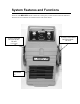
System Features and Functions The front of the MCS 352 cabinet contains the control panel, control switches and status indicators. The fuel reservoirs and filters are mounted on the sides of the cabinet.
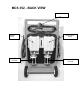
MCS 352 - BACK VIEW POWER CORD DIESEL TANK DIESEL FILTER GASOLENE TANK GASOLENE FILTER
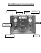
MCS 352 Control Panel Functions GASOLENE PRESSURE GAUGE ON/OFF SWITCH START/RUN SWITCH DIESEL PRESSURE GAUGE TIMER SERVICE SELECTOR SWITCH GASOLINE (PETROL) PRESSURE REGULATOR CIRCUIT BREAKER
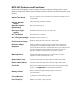
MCS 352 Features and Functions Descriptions of the gauges, control switches, and status indicators making up the control panel are listed below. Please become familiar with these features and functions before using the unit. Adjust Time Knob Sets or re-sets the system run time in one-minute increments, from 1 to 60 minutes. Service Selector Switch Start/Run Switch (Momentary) Selects fuel type: Diesel or Gasoline Run Cycle Light (green) On / Off Switch Illuminates when the run cycle is under way.
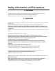
Safety Information and Precautions /!\ DANGER Vehicle exhaust gases contain Carbon Monoxide, which is a colorless and odorless lethal gas. Only run engines in well-ventilated areas and avoid breathing exhaust gases. Extended breathing of exhaust gases will cause serious injury or death. /!\ WARNING Exhaust gases, moving parts, hot surfaces, and potent chemicals are present during the use of the fuel system cleaner. Read and understand the operator’s manual before using the fuel system cleaner.
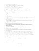
Chemicals can cause harmful byproducts. Use only approved chemicals (refer to operator’s manual). Do not swallow or ingest any chemicals. Use with adequate ventilation. Avoid breathing vapors. Do not store chemicals on or in the machine. Improper use of chemicals can cause injury. Over exposure can have harmful effect on eyes, skin, respiratory system and possible unconsciousness and asphyxiation. Improperly blocked vehicles can move. Set the parking brake and chock the wheels.
Batteries produce explosive gases and can explode. Wear safety goggles when working on or near batteries. Use in a well-ventilated area. Keep sparks and flames away from the battery and never lay tools, equipment or other conductive objects on the battery. When tools or equipment is connected to the battery, make sure the equipment power switch is off.
Before You Begin Gasoline (Petrol) Systems First Time Operation NOTE The following process is used to flush factorytesting fluids out of your new machine, and is only necessary before the first time you use the unit. 1. Verify that the fuel filter is connected and securely in place on the side of the cabinet. 2. Check the output/return hoses, battery connections, and all external components for damage. 3.
x 9. Press the ON/OFF switch to the on position. NOTE: Alarm will sound continually until pump starts. x Press and hold the START/RUN switch until the fuel from the unit has been emptied into the container. x Release the START/RUN switch. x Turn off the ON/OFF switch. x Dispose of the fuel in an environmentally approved method. The reservoir is now completely drained of fuel.
Filling Reservoir Procedure-NOTE: regulator valve must be open to allow flow for tank filling. Alternate-use black hose. FIGURE CARBURET OR THIS METHOD IS ALSO TYPICAL FOR RETURNLESS / SINGLE LINE FUEL INJECTION SYTEMS.
Fuel System Cleaning Procedures Gasoline (Petrol) Systems Determining the Vehicle's Fuel System Type It is very important to determine the fuel system type of the vehicle to be serviced before performing Any setup or cleaning procedure on the vehicle. The unit can be used with any of the four different types of gasoline fuel systems listed below: Carburetion Carburetors come in a variety of sizes and shapes. These can be easily identified by locating the choke plate in the air horn.
Carburetor Setup Procedure Follow the steps below to connect the unit to the vehicle's fuel system. Make sure the vehicle has at least 1/8 tank of fuel before beginning this process. 1. Start the vehicle and allow the engine to reach normal operating temperature. IMPORTANT Do not perform the setup or cleaning process if the vehicle’s engine oil or coolant level is low. If necessary, add oil and/or coolant to the vehicle. 2. Turn the vehicle OFF when normal operating temperature has been reached. 3.
/!\ WARNING Flammable Liquid can squirt out of pressurized lines when connecting or disconnecting. Wear Safety goggles. Obtain ZERO pressure before connecting or disconnecting any fuel lines or adaptors. Wear chemical resistant gloves when connecting or disconnecting fittings and adaptors. Wrap shop towel around pressure fittings and adaptors when disconnecting. Avoid exposure to flames, sparks, hot engine parts, and other ignition sources.
Carburetor Cleaning Procedure Follow the steps below to circulate the fuel/detergent mixture through the vehicle's carburetor. 1. Verify that Carburetor Setup Steps 1- 8 above have been completed. 2. Refer to the vehicle's service manual for the manufacturer's recommended pressure. 3. Adjust TIMER knob for 30 minutes. (Run time may be adjusted depending on the condition of the vehicle’s fuel system.) 4. Press the ON/OFF switch on. 5. Press and hold the START/RUN switch. 6.
13. Re-install the vehicle's gas cap. 14. Start the vehicle and verify that there are no leaks. 15. Test drive the vehicle for five kilometers (3 miles) immediately following the cleaning service to flush all detergent from the vehicle's fuel and exhaust systems.
Throttle Body Injection (TBI) Setup Procedure Follow the steps below to connect the unit to the vehicle's fuel system. Make sure the vehicle has at least 1/8 tank of fuel before beginning this process. 1. Start the vehicle and allow the engine to reach normal operating temperature. IMPORTANT Do not perform the setup or cleaning process if the vehicle’s engine oil or coolant level is low. If necessary, add oil and/or coolant to the vehicle. 2.
/!\ WARNING Flammable Liquid can squirt out of pressurized lines when connecting or disconnecting. Wear Safety goggles. Obtain ZERO pressure before connecting or disconnecting any fuel lines or adaptors. Wear chemical resistant gloves when connecting or disconnecting fittings and adaptors. Wrap shop towel around pressure fittings and adaptors when disconnecting. Avoid exposure to flames, sparks, hot engine parts, and other ignition sources.
Throttle Body Injection (TBI) Cleaning Procedure WARNING: BEFORE BEGINNING THE RAIL FLUSH PROCEDURE IT IS IMPORTANT TO TEST THE VEHICLE FOR INJECTOR LEAKDOWN. IF AN INJECTOR IS STUCK OPEN IT IS POSSIBLE TO DAMAGE THE ENGINE DUE TO ‘HYDROLOCK”. (LIQUID FILLING THE CYLINDER). IF THE VEHICLE HAS INJECTOR LEAKAGE DO NOT DO THE RAIL FLUSH, PROCEDE DIRECTLY TO THE ENGINE RUNNING-CLEANING PROCESS. RAIL-FLUSH PROCEDURE.
12. Turn the Gasoline (Petrol) PRESSURE REGULATOR counterclockwise on the unit to open it and release residual pressure. 13. Disconnect the battery leads, hoses, and adaptors. Return the vehicle's fuel system to its normal operating condition by re-connecting the vehicle's fuel lines. 14. Re-install the vehicle's gas cap. 15. Start the vehicle and verify that there are no leaks. 16.
Port Fuel Injection (PFI) Setup Procedure WARNING: BEFORE BEGINNING THE RAIL FLUSH PROCEDURE IT IS IMPORTANT TO TEST THE VEHICLE FOR INJECTOR LEAKDOWN. IF AN INJECTOR IS STUCK OPEN IT IS POSSIBLE TO DAMAGE THE ENGINE DUE TO ‘HYDROLOCK”. (LIQUID FILLING THE CYLINDER). IF THE VEHICLE HAS INJECTOR LEAKAGE DO NOT DO THE RAIL FLUSH, PROCEDE DIRECTLY TO THE ENGINE RUNNING-CLEANING PROCESS. Follow the steps below to connect the unit to the vehicle's fuel system.
/!\ WARNING Flammable Liquid can squirt out of pressurized lines when connecting or disconnecting. Wear Safety goggles. Obtain ZERO pressure before connecting or disconnecting any fuel lines or adaptors. Wear chemical resistant gloves when connecting or disconnecting fittings and adaptors. Wrap shop towel around pressure fittings and adaptors when disconnecting. Avoid exposure to flames, sparks, hot engine parts, and other ignition sources.
Port Fuel Injection (PFI) Cleaning Procedure Follow these steps to circulate the cleaning mixture through the Port Fuel Injection unit to clean the fuel rail, injector screens, and pressure regulator. 1. Verify that PFI Setup Steps 1-10 above have been completed before continuing. 2. Refer to the vehicle's service manual for the manufacturer's recommended pressure. 3. Adjust TIMER knob for 10 minutes. Press the ON/OFF switch on. 4. Press and hold the START/RUN switch. 5.
IMPORTANT Wrap a shop towel around pressure fittings before disconnection to protect against residual fuel spray. 13. Disconnect the battery leads, hoses, and adaptors. Return the vehicle's fuel system to its normal operating condition by re-connecting the vehicle's fuel lines. 14. Re-install the vehicle's gas cap. 15. Start the vehicle and verify that there are no leaks. 16.
Continuous Injection System (CIS) Setup Procedure WARNING: BEFORE BEGINNING THE RAIL FLUSH PROCEDURE IT IS IMPORTANT TO TEST THE VEHICLE FOR INJECTOR LEAKDOWN. IF AN INJECTOR IS STUCK OPEN IT IS POSSIBLE TO DAMAGE THE ENGINE DUE TO ‘HYDROLOCK”. (LIQUID FILLING THE CYLINDER). IF THE VEHICLE HAS INJECTOR LEAKAGE DO NOT DO THE RAIL FLUSH, PROCEDE DIRECTLY TO THE ENGINE RUNNING-CLEANING PROCESS. Follow the steps below to connect the unit to the vehicle's fuel system.
/!\ WARNING Flammable Liquid can squirt out of pressurized lines when connecting or disconnecting. Wear Safety goggles. Obtain ZERO pressure before connecting or disconnecting any fuel lines or adaptors. Wear chemical resistant gloves when connecting or disconnecting fittings and adaptors. Wrap shop towel around pressure fittings and adaptors when disconnecting. Avoid exposure to flames, sparks, hot engine parts, and other ignition sources.
Continuous Injection System (CIS) Cleaning Procedure Follow the steps below to circulate the cleaning mixture through the CIS fuel distributor to clean the pressure regulator and the top portion of the fuel distributor. 1. Verify that CIS Setup Steps 1-10 above have been completed before continuing. 2. Refer to the vehicle's service manual for the manufacturer's recommended pressure. 3. Adjust TIMER knob for 10 minutes. Press the ON/OFF switch on. 4. Press and hold the START/RUN switch. 5.
11. The unit will automatically shut off and the alarm will sound when the engine is stopped. Press off the ON/OFF switch. 12. Turn the Gasoline (Petrol) PRESSURE REGULATOR counterclockwise on the unit to release residual pressure. IMPORTANT Wrap a shop towel around pressure fittings before disconnection to protect against residual fuel spray. 13. Disconnect the battery leads, hoses, and adaptors.
Before You Begin Diesel systems First Time Operation The unit is tested at the factory with special test fluids then completely drained. These test fluids are compatible with diesel engine systems. Because the unit is dry during shipping, it will be necessary to prime the machine before it is put into service. 1. Fill the units fuel filter completely with diesel fuel, approximately 1quart (0.95 L). Verify that the unit’s fuel filter is securely in place on the unit. 2.
NOTE Repeat the above procedures any time the unit’s reservoir and filter are completely drained of fuel, unless filling from a premixed 1:1 ratio of detergent and diesel fuel mixture.
Diesel System Cleaning Procedures Filling and Mixture Setup Follow the steps below to obtain the proper fuel mixture for use during the cleaning procedure. Make sure the vehicle has at least 5 gallons (18.9L) of fuel before beginning this process. 1. Start the vehicle. Allow the engine to reach normal operating temperature if possible. NOTE: The diesel engine cleaning system should be operated on a level surface.
Filling Reservoir Procedure Figure A To pump diesel fuel into units tank, connect Red Hose to ball valve of 060-4500 tee adapter. Close ball valve. Start engine, check for leaks.
Purging Air from the System (Priming) It will be necessary to purge the air from the unit’s plumbing prior to connecting to the engine’s fuel system. 1. Connect the OUTPUT (RED) hose and the RETURN (BLACK) hose together using adapters 060-1400 and 060-1100, as shown in FIGURE B below. Secure with hose clamp. 2. Press SERVICE SELECTOR switch to DIESEL FUEL SYSTEM SERVICE. Turn TIMER past 5 minutes. Press ON/OFF switch to on. Press and hold the START/RUN switch.
Diesel Fuel System Setup Procedures 1. Start the vehicle and allow the engine to reach normal operating temperature (if possible). IMPORTANT Do not perform the setup or cleaning process if the vehicle’s engine oil or coolant level is low. If necessary, add oil and/or coolant to the vehicle. Stop the cleaning process if the engine is low on oil or overheats. 2. Turn the engine OFF when normal operating temperature has been reached. 3. If not already connected, attach the unit to a vehicle’s 12-Volt D.
NOTE Use an adaptor to plug off or loop back the fuel lines going to the tank to avoid any spills. NOTE Some fuel systems have two return lines: one from the injector pump and one from the injectors. When connecting to these types of systems, verify that both return lines have been captured. Usually they will join together at some point before going back to the tank. 6. As shown in FIGURE C on the next page, connect the appropriate adaptors at the points listed in Step 5.
Diesel Cleaning Setup FIGURE C You are now ready to perform the Diesel cleaning procedure.
Diesel Cleaning Procedures 1. Verify that Mixture, Priming, and Diesel Setup Procedures above have been completed before continuing. 2. Press SERVICE SELECTOR SWITCH to DIESEL FUEL SYSTEM and press the ON/OFF switch on after turning TIMER past five minutes. NOTE: Alarm will sound until pump starts. 3. Press and hold the START/RUN switch. The unit will start and the pressure should rise. The pressure can be checked by observing the FUEL PRESSURE gauge.
Shut Down 1. Just BEFORE the Run time expires, turn off the engine. During this time the pump will continue to run and supply fuel to the engine, when the TIMER expires, the pump shuts down. If the engine runs out of fuel, then it may be difficult to restart (especially if air is introduced into the fuel system). 2. Turn off unit’s ON/OFF switch. 3. Disconnect the system battery clips from the vehicle battery. 4.
Troubleshooting and Additional Help Refer to the list below in the unlikely event that you have problems with your MCS 352. Problem: Solution: 1. The MCS 352 is not operational or trips breaker immediately. Polarity is reversed on vehicle battery connection. Check connections for correct polarity. Check circuit breaker on the side of the cabinet. 2. Pressure Gauge on the MCS 352 displays maximum pressure upon start up. Output and Return hoses may be reversed.
ADDITIONAL HELP Please verify that items 1- 7 above have been reviewed before calling for additional assistance. In the unlikely event that problems persist with the MCS 352, call: Your Local Distributor Or: MOTORVAC TECHNOLOGIES INC. 1431 S. VILLAGE WAY SANTA ANA, CA 92705 USA PHONE: 714.558.4822 FAX: 714.558.0754 E-MAIL: Marketing@motorvac.com WEB SITE: www.CarbonClean.
Appendix A - Maintenance Maintenance Procedures The following maintenance procedures should be performed on a routine basis: 1. Drain the unit’s fuel reservoirs and replace the fuel filters after every 30 cleaning services for Gasoline (Petrol), or every 10 cleaning services for the unit’s diesel fuel reservoir for maximum performance as described in the next section. 2. Clean the exterior with a non-abrasive cleaning agent or similar product to keep the cabinet looking new.
Replace the Fuel Filter 1. Remove the old fuel filter from the mounting station on the side of the unit’s cabinet and install the new filter. Verify the filter is tightened securely. 2. Add the mixture back into the reservoir. 3. Check the filter for leaks. 4. Enter your initials, the date, and a check mark in the appropriate boxes of the Maintenance Record at the end of this chapter. The unit is now ready for the next cleaning service.
Initial/Date DRAIN FUEL RESERVOIR REPLACE FUEL FILTER CLEAN EXT.
Standard Adaptor Kit (200-3025A) The standard adaptor kit is included with your system. The most commonly used application is listed however, other applications may apply. PART & NO. QTY 2 060-1000 2 060-1100 2 APPLICATION GENERAL APPLICATIONS UTILIZING 1/4" FUEL LINE - MALE. (USE WITH SUITABLE HOSE CLAMPS.) GENERAL APPLICATIONS UTILIZING 5/16" FUEL LINE- MALE. (USE WITH SUITABLE HOSE CLAMPS.) GENERAL APPLICATIONS UTILIZING 3/8" FUEL LINE - MALE. (USE WITH SUITABLE HOSE CLAMPS.
1 060-2501 FORMS "TANK TO TANK" LOOP ON ALL VEHICLES. USED TO EXTEND VEHICLE'S RETURN LINE DURING DIAGNOSTICS. 1/4" MALE. 1 060-2800 1 060-3100 080-3402 (O-Ring) TBI AND/OR PORT FUEL PRESSURE LINE - MALE. G.M. VORTEC M16 x 1.5 1 060-3105 1 080-3302 060-3300 LATE MODEL VEHICLES TBI AND/OR PORT FUEL. (GM-CHRYSLER-JEEP/EAGLE). TBI AND/OR PORT FUEL PRESSURE LINE - FEMALE. G.M. VORTEC M16 x 1.5 TBI AND/OR PORT FUEL RETURN LINE - MALE. G.M. VORTEC M14 x 1.
PART & NO. QTY 1 060-3600 APPLICATION 1/2" MALE SPRING LOCK WITH CLIP (BLACK). PORT FUEL - PRESSURE LINE. FORD 080-3602 (O-Ring) 080-3601 (Clip) 1/2" FEMALE SPRING LOCK 1 060-3605 PORT FUEL - PRESSURE LINE. FORD 3/8" QUICK DISCONNECT 060-3901 1 PORT FUEL AND TBI 1 5/16" MALE TBI AND/OR PORT FUEL (GM-CHRYSLER-JEEP/EAGLE). 080-3904 (Clip) 060-4200 1 060-4300 1 060-3902 3/8" TBI AND/OR PORT FUEL (GM-CHRYSLER-JEEP/EAGLEFORD). 1/4" FEMALE TBI AND/OR PORT FUEL (GM-CHRYSLER-JEEP/EAGLEFORD).
Tee Adaptor For Single Line Fuel Injection Systems 060-4501 2 060-0440 060-0450 2 HOSE CLAMPS. USE WITH 0601000 THROUGH 060-1500.
Deluxe Adaptor Kit (200-3026A) The Deluxe adaptor kit is included with your system. The most commonly used application is listed however, other applications may apply. PART & NO. QTY 1 060-1600 1 060-1602 2 APPLICATION 12MM BANJO FITTING CIS OR EFI SYSTEMS. IN CONJUNCTION WITH 060-1900, 060-1901, 060-1902. 12MM 90q BANJO FITTING CIS OR EFI SYSTEMS. IN CONJUNCTION WITH 060-1900, 060-1901, 060-1902 14MM BANJO FITTING BMW AND LATE MODEL VW PRESSURE LINE.
3/8" QUICK DISCONNECT 060-3901 1 PORT FUEL AND TBI 1 3/8" TBI AND/OR PORT FUEL (GM-CHRYSLER-JEEP/EAGLE). 080-3904 (Clip) 060-4300 2 6 060-1900 060-1901 060-1902 (Bolt) (Washer) (Nut) 2 1 3 060-2740 060-2741 060-2742 (Bolt) (Washer) (Nut) CONNECTS 12MM BANJO FITTINGS FOR DIAGNOSTICS AND/OR CREATING A LOOP.
New / Optional GAS Adapters offered by MotorVac The following GAS adapters have been added to the CarbonClean adaptor line-up. The adapters listed are not included with any configured adapter sets & may be purchased separately from MotorVac Technologies, Inc. PART & NO.
10-32 x ½” 080-0593 060-3102 / Female Side 2000 & Newer Nissan Products (Includes Nissan Quest & Maxima)
I.C.S. (Intake Cleaning System) Kit Part Number – (200-8667, Red Bottle) One Kit Includes All Components Shown Below: Air Filler Housing, 100-5009 (Includes Viton Valve Core, 100-5010) (Includes Nylon Washer / Seal) Valve with 9’ Siphon Tube 100-5019 Black Plastic Bottle Neck 100-5034 Spray Tube 6” 100-5043 (Included with Spray Nozzle) Base O’Ring 100-5035 Spray Nozzle 100-5043 (Included with 6” Spray Tube) Spray Tube 30” with Nozzle 100-5044 Note; Knurled Nut is not available separately. I.C.S.
Appendix B - System Accessories Master Adaptor Kit (MV P/N 200-3031) Contact your Industrial Diesel Tune sales representative for information on obtaining the Master adaptor kit. The most commonly used application is listed; however, other applications may apply. PART & NO. QTY 2 060-1000 1 060-1100 2 060-1200 2 060-1300 1 060-1400 2 060-1500 GENERAL APPLICATIONS UTILIZING 1/4" FUEL LINE MALE. (USE WITH SUITABLE HOSE CLAMPS.) GENERAL APPLICATIONS UTILIZING 5/16" FUEL LINEMALE.
QTY PART & NO. APPLICATION 14MM BANJO FITTING 2 060-2402 1 FORMS “TANK TO TANK” LOOP ON ALL VEHICLES. 1 3 1 CONNECTS 14MM BANJO 060-2501 060-2740 060-2741 060-2742 (Bolt) (Washer) (Nut) 1/4" MALE NPT.
PART & NO. QTY APPLICATION 2 #6 X #4 FEMALE FLARE (45 ) COUPLER 2 GENERAL APPLICATIONS UTILIZING 3/16” FUEL LINE FEMALE. (USE WITH SUITABLE HOSE CLAMPS.