MOTORVAC TECHNOLOGIES INC. TRANSTECH-1000 Transmission Service System OPERATOR MANUAL UNIT MODEL NUMBER 500-1101 TRANSTECH 1000 OPERATOR MANUAL - 100-1101 Rev.
Table of Contents Introduction ...........................................................................................................................................3 Overview ................................................................................................................................................4 System Features and Functions...................................................................................................... 1-1 Control Panel Features and Functions.............
Introduction Congratulations on your selection of the TRANSTECH-1000 Transmission Service System. By choosing this product, you are acquiring the most technologically advanced method available for automatic transmission service fluid exchange. The TRANSTECH-1000 System is a self-contained system; designed to service any automatic transmission thru it’s’ dipstick tube.
Overview This manual contains all the information you need to use the TRANSTECH-1000 System. Please make sure all technicians using the unit read this manual and have it within easy reach whenever the unit is being used. The following is a quick reference to the information in this manual: System Features and Functions This chapter describes the TRANSTECH-1000 Transmission Service System’s Switches, Lights and Connections.
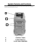
System Features and Functions The front of the TRANSTECH III cabinet contains the control panel, the fluid fill neck for adding new transmission fluid, and the fluid level windows. A B C A. B. C.
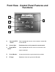
Front View - Control Panel Features and Functions A E B C D A. Vacuum-Off-Fill Switch. Turns on pump and activates valves to initiate vacuum, Fill or turn unit off. B. Vacuum light Illuminates when unit is powered in vacuum mode. C. Empty Waste switch Turns on pump and activates valves to evacuate the waste capture tank fluid. D. Circuit Breaker 15 amp circuit breaker to protect unit from overloads. E. Fill light Illuminates when unit is powered in Fill mode.
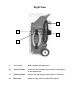
Right View C A D B A. Service Hose Fluid vacuum & fill supply hose. B. Quick Coupler Secures the unit’s output hose connection to the adapter for the dipstick tube. C. Battery Cables Positive (red) and negative (black) battery connections. D. Drain tray Adapter storage and excess fluid drain capture.
Theory of Operations Descriptions of the various operations, control buttons, and indicators that make up the control panel are listed below. VACUUM-OFF-FILL SWITCH: • When power cord is attached to a good 12 volt source, move the switch to the VACUUM position to create vacuum on the service hose. • When the switch is moved to the FILL position, the unit will pump fluid from the clean fluid tank out of the service hose.
Safety Information and Precautions /!\ DANGER Vehicle exhaust gases contain Carbon Monoxide, which is a colorless and odorless lethal gas. Only run engines in well-ventilated areas and avoid breathing exhaust gases. Extended breathing of exhaust gases will cause serious injury or death. /!\ WARNING Exhaust gases, moving parts, hot surfaces are present during and after the vehicle’s engine is running. Read and understand the operator’s manual before using the TRANSTECH Service system.
Over exposure can have harmful effect on eyes, skin, respiratory system and possible unconsciousness and asphyxiation. Improperly blocked vehicles can move. Set the parking brake and chock the wheels. Moving vehicles can cause injury. Moving engine parts. The engine cooling fan will cycle on and off depending on the coolant temperature and could operate without the engine running. Wear safety goggles. Always keep objects, clothing, and hands away from the cooling fans and engine parts.
Before You Begin First Time Operation NOTE This unit has been tested using Dextron lll Automatic Transmission Fluid, and is ready for service after receiving inspection of the unit. Use new oil above 50 degrees Fahrenheit. Remember to send in your warranty card. 1. Check the service hose, battery connections, and all external components for damage. 2. Fill the unit’s reservoir with 14 quarts (13 liters) of new transmission fluid if you are going to perform a service now. Otherwise use 8 quarts (7.
Transmission Service Procedure Follow the steps below to service the Transmission thru the dipstick tube. IMPORTANT Do not perform the transmission service if the vehicle’s engine oil or coolant level is low. If necessary, add motor oil and/or coolant. Do not perform service if new transmission fluid is below 50 degrees Fahrenheit. /!\ WARNING Flammable Liquid can squirt out of pressurized lines when connecting or disconnecting.
1. Add the correct amount of automatic transmission fluid into the TRANSTECH’S clean tank reservoir. See chart below: APPROXIMATED FLUSH CHART 4 Cylinder vehicle 6 Cylinder vehicle 8 Cylinder vehicle 10-12 quarts 12-14 quarts 14-16 quarts NOTE: Quantity of fluid used per vehicle may vary depending on the condition of the fluid in the transmission being serviced and the time allowed (engine running) between drain/fill sequences.
QUESTIONS & ANSWERS 1. How is the clean fluid tank completely emptied in order to change fluid type? The TransTech 1000 clean tank can be completely emptied. First connect the positive battery cable to a battery’s positive post. Connect the negative battery cable to the battery’s negative post. Install an adapter into the service hose. Insert the hose with adapter into a suitable container to capture the fluid from the clean tank. Turn on the FILL button.
Troubleshooting and Additional Help Refer to the list below in the unlikely event that you have problems with your TRANSTECH 1000 Transmission Service System. Problem: Solution: 1. Unit does not power-up. Inspect circuit breaker, reset if necessary. Check power cord for wiring breaks. 2. Pump runs but is not moving Check internal filters for obstruction. fluid. 3. Unit works in one mode but Possible problem with solenoid valves. not in others. 4. Unit will not start.
Appendix A - Maintenance Maintenance Procedures The following maintenance procedures should be performed on a routine basis: 1. Carefully clean the exterior with a soft cloth to keep the cabinet looking new. Check the cabinet for dents or impact markings, if found, inspect for damaged components. 2. Check all hoses and wires for cuts or frays. 3. Clean the unit’s filter screens after every 100 services or 6 months, which ever comes first. See the next section for procedure.
Maintenance Record Use the following table to keep a record of maintenance performed on the unit. Initial/Date / / / / / / / / / / / / / / / / / / I I I I I I I / DRAIN FLUID TANKS CLEANED FILTERS CLEAN EXT.
TransTech System Accessories Standard Adapter: TransTech 1000 Service Unit PART & NUMBER QTY 1 DESCRIPTION 36 inch WAND adapter (1/4” tubing) 060-xxxx ORDERING PARTS Parts for the unit may be ordered by calling Customer Service, have your model and serial numbers available: Call: 800.841.8810, 714.558.
Appendix C – Parts Service Parts for the TRANSTECH III Transmission System. Please refer to the part numbers below when ordering parts for this unit. Part # 010-0027 010-0026 040-0604 040-0507 010-5500 010-6100 010-6101 010-5004 010-5602 040-1200 040-2000 040-2200 010-6060 020-8043 020-1604 040-0612 040-0613 040-0623 050-1000 200-8665 080-0236 080-6009 100-1010 200-xxxx Description Wheel (8 x 1.75) Hub cap (Black Plastic) Cap Nut (½” ID – Push 0n) Axle Bushing (Black Nylon) Axle, Rear Wheels (½” x 20.