
Instructions


Dx350_05a_oi_e.doc / Mai-18 Seite 7 / 51
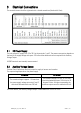
3 Electrical Connections
The terminal screws should be tightened with a slotted screwdriver (blade width 2mm).
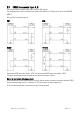
3.1 DC Power Supply
The unit accepts DC supply from 18 to 30 V at the terminals 1 and 2. The power consumption depends on
the level of the supply voltage with aprox. 100 mA and the additional current required at the Auxiliary
Voltage Output.
All GND terminals are internally interconnected.
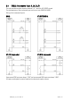
3.2 Auxiliary Voltage Output
Terminal 3 and 4 provide an auxiliary output for supply of sensors and encoders.
The output voltage depends on the power supply.
DC version
AC version
The encoder voltage is approx. 1 V lower than
the power supply voltage at terminal 1 and 2
and should be loaded with max. 250 mA.
The encoder voltage is 24 VDC (± 15%) and
should be loaded with max. 150 mA up to 45
degrees Celsius. At higher temperature the
maximum output current is reduced to 80 mA.
At DX355 devices, the auxiliary voltages output is switchable from 24 VDC to 5 VDC.