
User Manual


CUEMIX FX
87
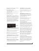
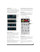
Compressor
The Compressor (Figure 9-21) lowers the level of
the input when it is above the threshold. The
amount of attenuation is determined by the Ratio
and the input level. If the input is 6 dB above the
Threshold and the Ratio is 3:1, then the output will
be 2 dB above the Threshold. When the input level
goes above the threshold, the attenuation is added
gradually to reduce distortion. The rate at which
the attenuation is added is determined by the
Attack parameter. Likewise, when the input level
falls below the Threshold, the attenuation is
removed gradually. The rate at which the
attenuation is removed is determined by the
Release parameter. Long Release times may cause
the audio to drop out briefly when a soft passage
follows a loud passage. Short Release times may
cause the attenuation to pump when the average
input level quickly fluctuates above and below the
Threshold.
These types of issues can be addressed by applying
the Leveler instead.
Graphic adjustment of the Threshold
The Threshold can be adjusted by turning the
Threshold knob or by dragging the Threshold line
directly in the compressor graph (Figure 9-21).
Input level meter
The Input Level meter (Figure 9-21) shows the level
of the input signal before it enters the compressor.
It shows either the peak level or the RMS level,
depending on which mode is currently chosen.
Gain reduction (GR) meter
The Gain reduction (GR) level meter (Figure 9-21)
displays the current amount of attenuation applied
by the compressor.
Output level
The Output Level meter (Figure 9-21) displays the
peaks of the output signal. Trim is applied before
the Output Level meter.
Peak/RMS modes
In RMS mode the compressor uses RMS values (a
computational method for determining overall
loudness) to measure the input level. In Peak mode,
the compressor uses signal peaks to determine the
input level. RMS mode will let peaks through
because the detector sidechain is only looking at
the average signal level. Peak mode will react to
brief peaks. Peak mode is generally used for drums,
percussion and other source material with strong
transients, while RMS mode is mostly used for
everything else.
The input meters show either the peak level or the
RMS level, depending on the mode.
Leveler
The Leveler™ (Figure 9-21) provides an accurate
model of the legendary Teletronix™ LA-2A®
optical compressor, known for its unique and
highly sought-after Automatic Gain Control
(AGC) characteristics. The 828x Leveler faithfully
models the LA-2A using the on-board DSP with
32-bit floating point precision.
A model of an optical compressor
The simplest description of an optical leveling
amplifier device is a light shining on a photore-
sistor. The intensity of the light source is
proportional to the audio signal, and the resistance
of the photoresistor is in turn inversely
proportional to the intensity of the light. Photore-
sistors respond quite quickly to increases in light
intensity, yet return to their dark resistance very
slowly. Thus, incorporation of the photoresistor
into an attenuator followed by an amplifier which
provides make-up gain produces a signal which
maintains a constant overall loudness.
Automatic gain control using light
The Automatic Gain Control (AGC) circuit of the
LA-2A uses a vintage opto-coupler known by its
model number (T4). The T4 contains an electrolu-
minescent panel (ELP) and photoresistor mounted