
User Manual-Mac


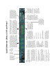
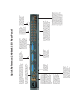


Quick Reference: 2408mk3 I/O Rear Panel
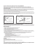
Connect the 2408mk3
to the PCI-424 card here
using the Audio Wire
cable provided with
your 2408mk3 system.
Connect up to three Tascam
digital recorders or other TDIF
compatible digital I/O devices to
these three connectors.
These jacks provide stereo SPDIF digital input and output. To use
them, choose the SPDIF format for one of the three banks in the PCI-
424 configuration window on your computer. Then assign the audio
tracks in your software to the SPDIF outputs that appear in its output
assignment menus.
These jacks also double as (analog audio) SMPTE time code inputs
and outputs. For complete details, see “Syncing to SMPTE time code”
on page 41 and chapter 14, “MOTU SMPTE Console” (page 117).
This is an extra SPDIF stereo output jack,
which carries a digital copy of the same
signal as the main outs and Analog 1-2.
You can connect it to whatever you
want. For example, you could connect it
to a DAT machine to record stereo
mixdowns of your 2408mk3 projects.
These two balanced, quarter-inch jacks serve
as the 2408mk3’s main outputs. They dupli-
cate the material from channels 1 and 2 of
the analog bank. To hear material from them,
choose “Analog” as the desired format for
one of the 2408mk3’s three banks (using the
PCI-424 configuration window on your
computer), and then assign any tracks you
want to hear to Analog channels 1-2. Use the
front panel MAIN OUT volume knob to
control the level from these outputs.
The 2408mk3’s eight analog inputs are gold-plated, balanced +4dB
TRS (tip/ring/sleeve) quarter-inch connectors. They have 24-bit,
64x oversampling converters. Each input pair can be set at +4dB or
-10dB via the PCI-424 configuration window on your computer.
Click the Interface Options button to access the input level settings.
Note that you can use one of these inputs for SMPTE time code
input, instead of the RCA connectors on the left side of the unit.
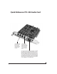
Use the word clock input and
output for digital transfers with
devices that cannot slave to the
clock supplied by their digital I/O
connection with the 2408mk3. Via
software, you can switch the word
clock output rate to either double
or halve the 2408mk3’s system
word rate. For example, if the
2408mk3 is running at 96 kHz, it
can transmit 48 kHz word clock
output.
The WORD IN connector can also
serve as a video input, which
allows the 2408mk3 to resolve to
video or blackburst. For details,
see “Syncing to video” on page 42
and chapter 14, “MOTU SMPTE
Console” (page 117).
Analog outputs 1 and 2 are dupli-
cated on the 2408mk3’s main
stereo outputs, as well as the
front panel stereo headphone
jack and the DAT SPDIF output.
Connect up to three ADATs or
other ADAT optical digital
I/O devices to these three
connectors. Be sure to
connect the optical cables
“OUT to IN” and “IN to OUT”.
If you want, you can connect both an
ADAT optical and a TDIF device to a
bank. They will share the same
output (regardless of which format
you choose on the computer), but you
can only record input from one format
or the other at a time per bank (as
chosen in the PCI Console software).
The 2408mk3’s eight
analog outputs are gold-
plated, balanced +4dB
TRS (tip/ring/sleeve)
quarter-inch connectors.
They have 24-bit, 128x
oversampling converters.