
User Manual


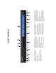
Table Of Contents
- Title Page
- Quick Start Guide
- 1248 Front Panel
- 1248 Rear Panel
- 8M Front Panel
- 8M Rear Panel
- 16A Rear Panel
- 16A Front Panel
- MOTU AVB Switch
- MOTU AVB Control Web App
- Overview
- It’s not on your hard drive
- Use your favorite web browser
- Control from multiple devices
- Run the installer, get the app
- Make hardware and network connections
- Launching the web app
- Device tab
- Device tab (continued)
- Routing tab
- Mixing tab
- Aux Mixing tab
- Mixer input channel strips
- Main Mix and Monitor channel strips
- Aux bus channel strips
- Group and Reverb channel strips
- 1 About Your MOTU AVB Audio Interface
- State-of-the-art A/D and D/A conversion
- Complementary I/O configurations
- 1248
- 8M
- 16A
- Network I/O
- Universal connectivity
- On-board DSP with mixing and effects
- 32-bit floating point processing
- Modeled vintage effects processing
- AVB system expansion and audio networking
- Matrix routing and multing
- 256 channels of network audio I/O for your host computer
- Web app control
- Stand-alone mixing with wireless control
- ADAT digital I/O
- S/PDIF digital I/O with SRC
- Word clock
- Comprehensive metering
- Headphone outputs
- Precision Digital Trim™
- Rack mount or desktop operation
- AudioDesk
- 2 Packing List and System Requirements
- 3 Software Installation
- 4 Hardware Installation
- Overview
- Rack installation and heat
- Thunderbolt audio interface setup
- USB audio interface setup
- Setup for two interfaces
- Setup for three to five interfaces
- Setup for a multi-switch network
- Setup for multiple Thunderbolt and USB interfaces
- Setup for web app control
- Audio connections
- A typical 1248 setup
- A typical 8M setup
- A typical 16A setup
- Synchronization
- Syncing S/PDIF devices
- Syncing word clock devices
- Syncing an AVB network
- 5 Presets
- 6 The Front Panel LCD
- 7 Working with Host Audio Software
- Overview
- Preparation
- Run the web app
- Sample rate
- Clock Mode
- Enabling and disabling input/output banks
- Specifying the number of computer channels
- Making inputs and outputs available to your host software
- Configuration presets
- Naming computer input and output channels
- Streaming computer audio to and from the onboard mixer
- Working with AVB network streams
- Mirroring computer channels to multiple outputs
- Combining multiple inputs to one output
- Routing grid tutorials
- Choosing the MOTU Audio driver
- Reducing monitoring latency
- Working with on-board mixing and effects
- Synchronization
- 8 Mixer Effects
- 9 Networking
- A Troubleshooting
- B Audio Specifications
- C Mixer Schematics
- D Updating Firmware
- E OSC Support
- Index

1248 Front Panel
1. MAIN OUT volume control. This setting, along with all
front panel settings, can also be adjusted from the
MOTU AVB Control web app.
2. MONITOR OUT volume control.
3. PHONE OUTPUTS with volume control.
4. GUITAR INPUTS with volume control. These are high-
impedance guitar inputs that provide authentic guitar
amp volume response and feel.
5. MIC INPUT preamp gain, switchable 48V phantom
power, and optional -20 dB pad switches for each mic
input. The Precision Digital Trim™ knob provides 63 dB
of preamp gain. Turn the knob to see the gain adjust-
ments on a large-scale, horizontal meter.
6. ANALOG INPUT METERS for the four mic inputs, two
guitar inputs, and eight balanced (TRS) quarter-inch
inputs on the rear panel.
7. ANALOG OUTPUT METERS for the eight balanced (TRS)
quarter-inch outputs, main outs, and monitor outs.
8. S/PDIF DIGITAL METERS (stereo input and output).
9. ADAT OPTICAL METERS. At 1x sample rates (44.1 or 48
kHz), there are sixteen channels of input and output. At
2x (88.2 or 96 kHz), there are eight channels.
10. The CLOCK section displays the current operating
sample rate and clock mode (source) for the unit.
11. POWER SWITCH: Thunderbolt, AVB, and USB are “plug-
and-play” protocols. That means you can turn the 1248
off and back on without restarting your computer.
12. The multi-purpose backlit LCD displays level meters for
all inputs and outputs. It can also show device settings
and network information, using the knobs to the left.
13. Push SELECT to enter the LCD menu. Turn SELECT to
scroll through menu options. Push again to descend
into the submenus, if applicable. To choose the current
setting, push SELECT a third time. Push BACK to return
to the previous menu level, and do so repeatedly to exit
the menu altogether.
14. Push ID to display network settings for the device,
including its IP address.
15. Push TRIM to enter trim mode. In this mode, the LCD
numerically displays gain settings for eight channels at
a time. Use the front panel knobs to adjust each
channel, from left to right, starting with the MAIN
volume knob.
121314
1065431 2 7 8 9 11
15