
Instruction manual

USING MIDI TIMEPIECE AV CONSOLE
92
panel. For details on setting up LRC control of the
MIDI Timepiece AV, see “Using an Alesis LRC-
compatible controller” on page 133.
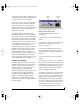
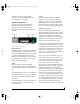
FILTER WINDOW
The Filter window is used to filter unwanted MIDI
data passing through the ports of the MIDI
Timepiece AV. Both inputs and outputs have filter
settings and each port’s settings is independent of
the others. A port’s Filter window is divided into
two sections. The upper section contains filter
settings for “channelized” MIDI messages (those
that are sent on a particular MIDI channel, such as
“note” or “Pitch Bend” messages) and the lower
part contains filter settings for “non-channelized”
MIDI messages (those that are not sent on a
particular channel, such as “System Exclusive”
messages).
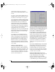
Figure 10-12: The Filter window for the input named “K2500”.
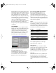
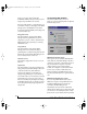
Changing a filter setting
To filter MIDI messages for a particular port:
1 Click on the port’s icon in the MIDI Routing
window.
2 With the port selected, click on the “filter”
button above the selected port.
3 Now, with the port’s Filter window open, adjust
the message check boxes so the MIDI
Timepiece AV performs your desired message
filtering as explained below in Figure 10-13.
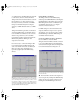
Figure 10-13: A red “X” means data will be filtered. A green check
mark means the data will not be filtered. A “hatched out” box
indicates that data is both filtered on one or more channels and not
filtered on one or more channels. The non-channelized filters will
never show the hatched-out box, since they apply to all channels.
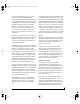
Filtering channelized messages
Each channel in the Channelized section has its
own filtering settings. Think of the channel
selection as letting you step through the 16
different filter combinations on each channel on a
particular port (as conceptualized in
Figure 10-14).
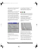
Figure 10-14: The channel settings in the Filter window lets you have
“layers” of filtering. Each channel has its own filter settings.
☛ When “All” is selected as the channel,
adjusting the message check boxes affects the
filtering of the messages on every channel. Under
this circumstance, the check boxes have a third
state (a “hatched-out” box as shown in
Figure 10-13) to indicate that a message is both
filtered on one or more channels and not filtered on
one of more channels. When the check box
contains an “X”, the message is filtered on all
channels and when it contains a “check” the
message is not filtered on any channel. You may
!USB Interfaces Manual Book Page 92 Tuesday, October 10, 2000 12:43 PM