LP32 ™ User Guide Title Page 1280 Massachusetts Avenue Cambridge, MA 02138 Business voice: (617) 576-2760 Business fax: (617) 576-3609 Web site: www.motu.com Tech support: www.motu.
SAFETY PRECAUTIONS AND ELECTRICAL REQUIREMENTS FOR THE LP32 (“PRODUCT”) CAUTION! READ THIS SAFETY GUIDE BEFORE YOU BEGIN INSTALLATION OR OPERATION. FAILURE TO COMPLY WITH SAFETY INSTRUCTIONS COULD RESULT IN BODILY INJURY OR EQUIPMENT DAMAGE. HAZARDOUS VOLAGES: CONTACT MAY CAUSE ELECTRIC SHOCK OR BURN. TURN OFF UNIT BEFORE SERVICING. WARNING: TO REDUCE THE RISK OF FIRE OR ELECTRICAL SHOCK, DO NOT EXPOSE THIS APPLIANCE TO RAIN OR OTHER MOISTURE.
Contents Part 1: Getting Started 7 Quick Start Guide 9 LP32 Front Panel 10 LP32 Rear Panel 11 MOTU Pro Audio Control Web App 23 About the LP32 27 Packing List and System Requirements 29 Software Installation 33 Hardware Installation Part 2: Using the LP32 49 Presets 53 The Front Panel LCD 55 Working with Host Audio Software 63 Mixer Effects 71 MOTU Audio Tools 87 Networking Part 3: Appendices 95 Troubleshooting 97 Audio Specifications 99 Mixer Schematics 103 Updating Firmw
About the Mark of the Unicorn License Agreement and Limited Warranty on Software TO PERSONS WHO PURCHASE OR USE THIS PRODUCT: carefully read all the terms and conditions of the “click-wrap” license agreement presented to you when you install the software. Using the software or this documentation indicates your acceptance of the terms and conditions of that license agreement. Mark of the Unicorn, Inc. (“MOTU”) owns both this program and its documentation.
Part 1 Getting Started
Quick CHAPTER Start Guide Thank you for purchasing an LP32! Follow these easy steps to get started quickly. ■ For advanced network options, and device discovery from any modern browser, see chapter 10, “Networking” (page 87). 1 Download and run the MOTU Pro Audio Installer found here: http://www.motu.com/avb 2 (Optional) For quick access to the LP32 from your iPad or iPhone, download the MOTU Discovery app from the Apple App Store.
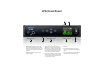
LP32 Front Panel 7 1 1. HEADPHONE OUTPUT with volume control. The LCD provides visual feedback with a volume meter. Doubletap the knob to mute/unmute. Hold in the knob to lock the volume meter on screen; hold it in again to unlock and dismiss. 2. Push ID to display network settings for the device, including its IP address. 2 3 3. Push SEL (select) to enter the LCD menu. Push the ARROW buttons to scroll through menu options. Push SELECT again to descend into the submenus, if applicable.
LP32 Rear Panel 1 4 2 3 5 1. This jack accepts any standard 12-18V DC power supply (1.0A max) with tip-positive polarity. 2. BNC word clock jacks. Use them for a variety of applications, such as digital transfers with devices that cannot slave to the clock supplied by their digital I/O connection with the LP32. 3. These four independent banks of ADAT optical “lightpipe” provide 8 channels each of 24-bit ADAT optical digital I/O at 1x sample rates (44.
MOTU Pro Audio Control Web App CHAPTER OVERVIEW MOTU Pro Audio Control is a web app that gives you complete control over the LP32. If you have several MOTU AVB interfaces networked together, such as the LP32, 1248 and 8M, you can control them all. If you are working with a large network of many MOTU AVB interfaces, you can access any device on the network. MAKE HARDWARE AND NETWORK CONNECTIONS Connect your LP32 to your computer or laptop with a USB cable.
DEVICE TAB 6 7 8 9 10 5 11 12 4 3 2 13 14 1 15 19 18 Windows only 17 16 1. If you have two or more MOTU interfaces, the Devices list lets you choose the one you are currently controlling with the web app. 2. The Aux Mixing tab lets you view each Aux bus in the mixer, one at a time. 3. The Mixing tab gives you access to the mixing and DSP in the interface. 4.
DEVICE TAB (CONTINUED) 21 20 22 24 23 Scroll down to view these additional Device tab settings. 20. AVB is IEEE’s Audio Video Bridging Ethernet standard for highbandwidth, low-latency audio streaming over Ethernet. If your MOTU interface is connected to a 2nd MOTU interface through its network port, or to an AVB switch for access to an extended AVB network, you can stream audio channels to and from other devices on the network.
DEVICE TAB (CONTINUED) 25 26 30 27 28 31 29 Scroll down to view these additional Device tab settings. 25. In the Computer Setup section, you can specify how many audio channels you would like to be able to stream to and from your computer, up to 64 channels each way, simultaneously, over USB. Map them as desired in the Routing tab (page 15). 26.
ROUTING TAB 4 5 6 7 8 9 10 11 3 12 2 13 14 15 1 21 20 16 19 18 17 The Routing Tab lets you route inputs to outputs. Outputs are listed by row on the left; inputs are listed in columns across the top. Simply click in the grid to make a single connection. Click and drag to make multiple connections in one gesture. To route a single input to multiple outputs, make multiple connections vertically in the same column below the input.
MIXING TAB 3 4 5 6 7 8 9 10 11 12 13 14 15 16 2 17 1 18 19 32 31 20 30 29 21 22 28 23 24 25 27 The Mixing tab gives you full access to the 48-channel mixer in the LP32, which provides a main mix bus, monitor bus, three group busses, seven aux busses, and a dedicated reverb bus. Use the Device tab to configure how many inputs you wish to work with (up to 48). Use the Routing tab (page 15) to route channels to the mixer inputs.
AUX MIXING TAB 3 4 5 6 7 8 9 10 2 1 17 11 12 13 16 15 14 The Aux Mixing tab provides quick access to the LP32’s mix busses (aux busses, groups and reverb bus), viewed one at a time. Choose a bus in the Aux Mix Target section and then use the faders to directly mix the send levels from all mixer inputs, groups, and the reverb bus. 4. Click the aux bus or group you wish to view in the window. In this example, Aux bus 1-2 is being displayed. 5.
MIXER INPUT CHANNEL STRIPS 1 2 6 7 8 4 5 To access a mixer input channel strip, go to the Mixing tab (page 16), reveal the side bar (item #3 on page 16), and then show the input channel you want in the Mixer Inputs section (31). To show and hide sections of the channel strip, such as EQ or the compressor, use the Controls section of the side bar (item #3 in the Mixing tab on page 16). 30 29 3 2 9 3 1. Click the input channel name to change it. Delete the current name to restore the default name.
MAIN MIX AND MONITOR CHANNEL STRIPS 1 2 3 4 3 5 6 4 5 7 15 To access the Main Mix and Monitor bus channel strips, go to the Mixing tab (page 16) and scroll the display to the right, beyond the inputs and groups. To show and hide sections of the channel strip, such as EQ or the Leveler, use the Controls section of the side bar (item #3 in the Mixing tab on page 16). 8 9 1. By default, the Monitor bus serves as a solo bus.
AUX BUS CHANNEL STRIPS 1 11 2 3 Aux busses can be used to create sub-mixes. An aux bus can be assigned to any output in the Routing grid (page 15). 4 To access an Aux bus channel strip, go to the Mixing tab (page 16), reveal the side bar (item #3 on page 16), and then show the aux busses you want in the Mixer Outputs section (28). To show and hide the four-band EQ section of the channel strip, use the Controls section of the side bar (item #3 in the Mixing tab on page 16). 10 1. A stereo aux bus. 2.
GROUP AND REVERB CHANNEL STRIPS 1 2 10 3 Group busses can be used to create a mix subgroup, which is a set of inputs you wish to control together as a group. Groups differ from aux busses in that they have aux sends, a reverb send, as well as a main mix send. In addition, group busses are equipped with the Leveler. The Reverb bus is a special group bus that provides a reverb processor. If you disable the reverb, the reverb bus functions as a (fourth) regular group bus.
MOTU PRO AUDIO CONTROL WEB APP
CHAPTER 1 About the LP32 The LP32 is a flexible ADAT optical “lightpipe” audio interface, router, splitter, converter and stand-alone mixer with AVB-TSN networking and connectivity to a host computer through class compliant, high-speed USB 2.0 (compatible with USB 3.0 and iOS). The LP32 provides four independent banks of 8-channel ADAT optical I/O, 64 channels of USB I/O, 32 channels of AVB-TSN network I/O and a headphone output, for a total of 258 simultaneous I/O channels.
Alternately, the LP32 can be connected to the Ethernet port on a recent-generation Mac (any Mac with Thunderbolt on it) running Mac OS X El Capitan (10.11) or later for audio interface operation through AVB Ethernet. extended bank of I/Os for your computer-based production system (or both). You can even connect multiple computers, each with full access to all devices on the network (including the other computers).
Comprehensive metering The color LCD displays all signal activity at a glance with detailed metering for all I/O. You can access many hardware settings directly from the front panel. Headphone output The LP32 front panel provides an independent headphone jack with separate volume control. You can program the phones to mirror another set of outputs or act as its own independent output. Rack mount or desktop operation The LP32 is housed in a sturdy, metal-alloy halfrack enclosure.
ABOUT THE LP32
CHAPTER 2 Packing List and System Requirements PACKING LIST PLEASE REGISTER TODAY! the LP32 ships with the items listed below. If any of these items are not present in the box when you first open it, please immediately contact your dealer or MOTU. Please register the LP32 today. There are two ways to register.
PACKING LIST AND SYSTEM REQUIREMENTS
CHAPTER 3 Software Installation OVERVIEW USB audio class-compliant operation. . . . . . . . . . . . . . . . Software installation. . . . . . . . . . . . . . . . . . . . . . . . . . . . . . . . . Audio drivers . . . . . . . . . . . . . . . . . . . . . . . . . . . . . . . . . . . . . . . . MOTU Discovery app . . . . . . . . . . . . . . . . . . . . . . . . . . . . . . . . MOTU Pro Audio WebUI Setup for Windows . . . . . . . . . MOTU Audio Tools . . . . . . . . . . . . . . . . . . . . . . . . . . . . . . . .
AUDIO DRIVERS The installer provides USB audio drivers for Mac (CoreAudio) and Windows (ASIO and Wave). Industry-leading I/O latency performance On OS X and Windows, the MOTU Pro Audio driver provides exceptionally low I/O latency performance for USB operation. For example, with a 32-sample buffer size, an LP32 interface operating at 96 kHz produces round trip latency (RTL) performance of 1.63 milliseconds (ms) over USB on Windows and 1.61 ms on OS X.
Host Safety Offset When connected to a Windows host, the Host Safety Offset menu (Figure 3-2) also becomes available. This setting allows you to fine tune host latency. Larger offsets allow the driver more time to process audio as it transfers to and from the hardware. Lower settings produce lower latency, but if you go too low, your host software may experience performance issues. Generally speaking, 48 samples should serve as a good baseline setting. You can then experiment with lower settings from there.
SOFTWARE INSTALLATION
CHAPTER 4 Hardware Installation OVERVIEW USB or iOS audio interface setup . . . . . . . . . . . . . . . . . . . . 33 AVB Ethernet audio interface setup. . . . . . . . . . . . . . . . . . 34 Setup for two interfaces . . . . . . . . . . . . . . . . . . . . . . . . . . . . . 34 Setup for three to five interfaces. . . . . . . . . . . . . . . . . . . . . 35 Setup for a multi-switch network . . . . . . . . . . . . . . . . . . . . 36 Setup for multiple interfaces. . . . . . . . . . . . . . . . . . . . . . . . .
AVB ETHERNET AUDIO INTERFACE SETUP SETUP FOR TWO INTERFACES OR Use this setup if you want to use the LP32 as an AVB Ethernet audio interface for a recent-generation Mac (i.e. any Mac with a Thunderbolt port on it). OS X El Capitan (10.11) or later is required for AVB audio I/O. ■ Use a standard CAT-5e or CAT-6 cable. ■ Connect to the computer’s Ethernet port. See “Setup for AVB Ethernet audio interface operation” on page 40. Use this setup if you want to connect two MOTU interfaces to your computer.
SETUP FOR THREE TO FIVE INTERFACES Use this setup if you want to connect three to five MOTU interfaces to your computer using a MOTU AVB Switch™ (sold separately). ■ The connection to the computer can be USB or Thunderbolt (if you have a Thunderbolt-equipped MOTU AVB interface). Use Thunderbolt or USB 3.0, if possible, to support a large number of audio streams to and from the networked interfaces. A single Thunderbolt or USB 3.0 connection supports 128 channels in and out, simultaneously.
SETUP FOR A MULTI-SWITCH NETWORK ■ You can daisy-chain switches in serial fashion, but don’t create loops. For example, switches A, B, and C below are chained properly, but don’t connect C back to A. Alternately, you could connect both Switches B and C to Switch A. Use this setup if you want to connect more than five MOTU interfaces to an extended network that employs multiple AVB switches. AVB Ethernet is an industry standard, so you can use MOTU AVB Switches or 3rd-party AVB switches.
SETUP FOR MULTIPLE INTERFACES It is possible to connect multiple MOTU interfaces directly to your host computer through multiple USB (and Thunderbolt) ports. However, there are several disadvantages to using any of these direct connection schemes: The audio interfaces will not be clocked to one another and may be susceptible to drift, unless you use external word clock connections (if available). You are better off using the AVB network connections shown on pages 34-36.
The web app is a web application served by the hardware. All you need to run it is a web browser running on a device that has a connection to your audio interface through USB or a shared network. Web app in your browser Web app Figure 4-1: The web app is served from the hardware, and accessed through any web browser on any device connected to the interface.
Ethernet cable A simple Ethernet cable connection can be used for web app control, even without a USB connection to your computer. For example, if you are using your MOTU device as a mixer or audio router, you could control the on-board routing, mixing and effects from the web app through a standard Ethernet connection. Wi-Fi When using standard Wi-Fi as shown, you can control the LP32 from multiple Wi-Fi devices simultaneously.
SETUP FOR AVB ETHERNET AUDIO INTERFACE OPERATION Your MOTU hardware can serve as an Ethernet audio interface when connected to a recent generation AVB-equipped Mac. You can then use your MOTU interface as a standard multi-channel audio interface with any Core Audio compatible host software running on the Mac. 1 Launch the MOTU Discovery app.
☛ MOTU interfaces currently only support 8-channel streams (or less) so be sure to avoid configurations with streams that have more than eight channels. Figure 4-10: Routing Mac channels to physical outputs. Figure 4-8: Choosing an AVB configuration for the Mac. 7 For Recording to the Mac, route desired physical inputs on your MOTU interface to output streams. 4 From the Sample Rate menu (Figure 4-7), choose the desired sample rate. Currently, the Mac only supports 48, 96 and 192 kHz sample rates.
AUDIO CONNECTIONS Here are a few things to keep in mind as you are making audio connections to your LP32 interface. Optical I/O The LP32 provides four banks of ADAT optical (“lightpipe”) connectors (one input and one output each). Together, they provide 32 channels of ADAT optical digital I/O at 44.1 or 48 kHz, or 16 channels of industry standard SMUX optical at 2x sample rates (88.2 or 96 kHz).
Not phase-locked Phase-locked Device A Device B Figure 4-13: When transferring audio, two devices must have phaselocked audio clocks to prevent clicks, pops or other artifacts. There are two ways to achieve phase lock: slave one device to the other, or slave both devices to a third master clock. If you have three or more digital audio devices, you need to slave them all to a single master audio clock.
Daisy-chaining word clock If necessary, you can daisy-chain several word clock devices together. When doing so, connect WORD CLOCK OUT from the first (master) device to the WORD CLOCK IN on the second device. Then connect its WORD CLOCK THRU port to the next device’s WORD CLOCK IN port, and so on. On the LP32, use its WORD CLOCK OUT port and change its operation from OUT to THRU in the Device tab of the MOTU Pro Audio Control web app (item #15 on page 12).
Resolving the master clock device to an external clock source The MOTU device you’ve specified as the AVB network clock master can itself be resolved to an external time base such as word clock or optical (if available). Just choose the desired clock source from its Clock Mode menu (in the Device tab). Doing so effectively resolves the entire AVB network to the external clock source.
HARDWARE INSTALLATION
Part 2 Using the LP32
CHAPTER 5 Presets OVERVIEW AUDIO INTERFACE Because of its advanced, extensive feature set, the LP32 can be used for many different purposes. This chapter discusses common use cases and their corresponding device presets, to help you use the hardware for your needs. Choose the Audio Interface preset to use the LP32 as a standard USB or iOS audio interface. Hardware inputs and outputs are accessible from your computer or iOS device.
STAND-ALONE MIXER INTERFACE + MIXER Choose the Stand-alone mixer preset to use the LP32 as a mixer. Doing so routes all physical inputs to the mixer, with the mixer’s main mix bus going to Headphone Out L-R. If needed, you can use the routing grid to also send the main mix to any optical output pair on any bank, or even multiple output pairs. Choose the Interface + Mixer preset to use the LP32 as both an audio interface and mixer, simultaneously.
LIVE RECORDING + AVB Choose the Live recording + AVB preset for tracking. It is similar to the Interface + Mixer preset, except that it includes two 8-channel AVB network streams, with all 16 incoming network channels routed to both the computer and the mixer. All optical inputs on the interface are also routed to both the computer (for recording) and the Main Mix in the mixer (for near-zero latency monitoring).
PRESETS
CHAPTER 6 The Front Panel LCD OVERVIEW HEADPHONE VOLUME KNOB The front panel LCD displays level meters for all inputs and outputs and activity indicators for network I/O. The LCD also provides several menus that provide status information and basic hardware settings. The headphone volume knob (Figure 6-2) is a push-button digital rotary encoder. Push the knob for the features discussed below. Level meters . . . . . . . . . . . . . . . . . . . . . . . . . . . . . . . . . . . . . . . . .
Main Menu Push the up/down arrow buttons to scroll through the menu settings in the LCD. Settings menu The Settings menu provides access to basic hardware settings. Push SEL to enter the selected sub-menu or to select the currently highlighted parameter. Setting What it does Clock Mode Sets the digital audio clock source for the device. Push BACK to go to the parent menu. Sample Rate Sets the sample rate for the device.
CHAPTER 7 Working with Host Audio Software OVERVIEW RUN THE WEB APP The LP32 provides multi-channel audio input and output for Core Audio compatible audio applications on the Mac and ASIO or Wave compatible applications on Windows, including MOTU’s Digital Performer and AudioDesk, Apple’s Logic Pro and GarageBand, and other third-party software applications such as Ableton Live, Avid Pro Tools, Cockos Reaper, Propellerhead Reason, Steinberg Cubase and Nuendo, Cakewalk SONAR, PreSonus Studio One, Bitwig,
For Mac OS X audio software For audio software running under Mac OS X, go to the menu item or preference where you choose the audio device (Core Audio driver) you wish to use, and then select the LP32 by name. For Windows audio software For audio software running under Windows, go to the menu item or preference where you choose the ASIO driver you wish to use, and then choose MOTU Pro Audio. If your host audio software doesn’t support ASIO, choose the MOTU Pro Audio Wave driver instead.
Monitoring through the LP32 If you don’t need to process a live input with plug-ins, the easiest way to avoid monitoring latency is to disable your DAW’s live monitoring feature and instead use the digital mixer in the LP32 to route the input directly to your outputs. For details, see “Mixing tab” on page 16. The mixer in the LP32 even provides zero latency effects processing (EQ, compression and reverb), which can be applied to the signal.
Adjusting buffer size on Mac OS X Under Mac OS X, audio I/O buffer size is handled by the host audio application (not by the LP32’s Core Audio driver). Most audio software applications provide an adjustable audio buffer setting that lets you control the amount of delay you’ll hear when monitoring live inputs or processing them with software plug-ins. Here are a few examples. Figure 7-4: In Logic Pro, go to the Audio Driver preferences to access the Buffer Size option shown above.
Figure 7-5: When adjusting the buffer size to reduce monitoring latency, watch the ‘processor’ meter in Digital Performer or AudioDesk’s Performance Monitor. If you hear distortion, or if the Performance meter is peaking, try raising the buffer size. If you are at a point in your recording project where you are not currently working with live, patchedthru material (e.g. you’re not recording vocals), or if you have a way of externally processing inputs, choose a higher buffer size.
Specifying the number of computer channels In the web app Device tab (page 14), in the Computer Setup section, you can specify the number of computer channels for streaming audio to and from your host audio software. You might want enough channels to cover the following: ■ Physical inputs you want to record on your computer. ■ The physical outputs you want to send audio playback to. ■ Any audio streams going to and from the on-board mixer in your MOTU device.
Streaming computer audio to and from the on-board mixer In the Routing grid, you’ll see mixer inputs across the top of the grid, including Main, Monitor, Aux, etc. (item 11 on page 15). These are output busses from the LP32’s on-board mixer. To route one of these mix busses to your host computer software, click the grid at the intersection of the mix column and desired computer channel row. Now, the mix bus output will be routed to the computer via the channel you selected.
WORKING WITH HOST AUDIO SOFTWARE
CHAPTER 8 Mixer Effects OVERVIEW Leveler . . . . . . . . . . . . . . . . . . . . . . . . . . . . . . . . . . . . . . . . . . . . . . . 67 This chapter provides further information about the effects processors available in the DSP mixer in the LP32. For basic mixer operation, see: The Leveler™, an accurate model of the legendary LA-2A optical compressor, which provides vintage, musical automatic gain control Mixing tab . . . . . . . . . . . . . . . . . . . . . . . . . . . . . . . . . . . . . . . . . .
GATE All input channel strips provide a Gate module. Enabling EQ Each band has an enable/disable button (Figure 8-3), allowing you to enable as few or as many bands as needed for the channel strip. Figure 8-2: The Gate module. Enable/disable The gate silences the signal when the input signal’s level drops below the Threshold. The rate at which the gate responds, (opens to let signal through) is determined by the Attack parameter.
sculpting. The four-band EQ has been designed to be flexible enough to cover a broad range of applications. By adjusting Gain and Bandwidth together, you can emulate the smooth and musical character of classic analog EQ circuits, in which the Gain/Bandwidth dependency was dictated by the actual circuit design and electrical components used. COMPRESSOR All mixer input channel strips provide a compressor module.
the signal to 2 dB above the Threshold. When the input level goes above the threshold, the attenuation is added gradually to reduce distortion. The rate at which the attenuation is added is determined by the Attack parameter. Likewise, when the input level falls below the Threshold, the attenuation is removed gradually. The rate at which the attenuation is removed is determined by the Release parameter. Long Release times may cause the audio to drop out briefly when a soft passage follows a loud passage.
LEVELER The Leveler™ (Figure 8-7) provides an accurate model of the legendary Teletronix™ LA-2A® optical compressor, known for its unique and highly sought-after Automatic Gain Control (AGC) characteristics. Figure 8-7: The Leveler module. The Leveler is available on the Main Mix bus and all Group busses, including the Reverb bus. A model of an optical compressor An optical leveling amplifier works by shining a light on a photoresistor.
Enabling or disabling the Leveler The Leveler models the LA-2A so closely, it also models the time it takes for an actual LA-2A to “warm up” after it is turned on. Therefore, when you enable the Leveler, give it a moment to “settle” before you begin processing signals with it. Gain Reduction Gain Reduction (Figure 8-7) sets the strength of the signal sent to the AGC model. Makeup Gain Makeup gain (Figure 8-7) amplifies the output signal to make up for gain reduction.
setting represents the bottom frequency of the Mid band. The Ratio determines the length for each band specified in a percentage of the low frequency reverb time. DSP USAGE The DSP Usage meter (item #30 on page 18) shows how much of the available DSP processing power is currently being used by the mixer for the mix and for effects processing. If there aren’t enough DSP resources for all effects to be enabled on a channel, effects are disabled for that channel and all subsequent channels.
MIXER EFFECTS
CHAPTER 9 MOTU Audio Tools The MOTU Audio Tools application provides advanced audio analysis tools, which can be applied to a left channel input, right channel input, or both. Installation. . . . . . . . . . . . . . . . . . . . . . . . . . . . . . . . . . . . . . . . . . . Device menu. . . . . . . . . . . . . . . . . . . . . . . . . . . . . . . . . . . . . . . . . Analysis menu . . . . . . . . . . . . . . . . . . . . . . . . . . . . . . . . . . . . . . . Left/right input . . . . . . . . . . . . . . . . .
ANALYSIS MENU Choose the desired form of audio analysis from the Analysis menu (Figure 9-1). For details on each analysis pane, see the following sections of this guide. LEFT/RIGHT INPUT Choose the desired channel(s) you wish to scope from the Left Input and Right Input menus (Figure 9-1). These menus display the To Computer channels configured in the MOTU Pro Audio Control web app. The number of channels shown is controlled by the From device to computer setting in the Device tab.
View controls You can show and hide the FFT display and spectrogram as desired using the View controls (Figure 9-5). Pause button View menu Display options Figure 9-5: FFT view controls. View menu This menu provides various options for displaying the two input channels. View menu setting What it does Left Displays the left channel only. Right Displays the right channel only. Split Screen H Shows both channels side by side, with the screen split horizontally.
OSCILLOSCOPE Vertical controls menu The Oscilloscope (Figure 9-9) graphs the amplitude of an audio signal over time. Figure 9-7: The Vertical controls. In Zoom/Offset mode, Zoom sets the display zoom from 1x to 100x, and Pos sets the center amplitude of the graph. In Min/Max mode, Min and Max set the smallest and largest displayed amplitude. Spectrogram controls The Floor control (Figure 9-8) sets the amplitude threshold for the spectrogram display, from -144 dB up to 0 dB.
View menu The View menu (Figure 9-10) lets you choose how to display the audio channel(s) being displayed.
Type I recognition provides the most stable display of the waveform. It is the most resistant to change. Louder transients, such as those produced by a snare drum, are not displayed inside of the waveform window. Type I is best for observing the shape of a signal produced by a synthesizer or observing the tone of a guitar through a chain of pedals. Type II recognition is less resistant to change. It will include loud transients within the waveform recognition window.
Trigger modes The Trigger menu (Figure 9-12) provides four modes: Trigger indicator re-arms the trigger. When the Trigger mode is None, clicking on the Trigger indicator has no effect. Trigger mode What it does Measurement information You can view detailed information about a particular time range by using the measurement bars (Figure 9-9). None The Trigger is not active; this is the default mode. The incoming audio signal will be displayed continuously as audio is received.
snare hit, as you make adjustment the compressor, you can see the transient waveform change the next time the Oscilloscope triggers. For compression, this can be particularly useful for balancing the effect of the attack on the transient, relative to the decay portion of the waveform. Conversely, you can see the effect of the threshold setting directly on the decay portion, relative to the attack. In effect, you can see as well as hear the results of your compression adjustments.
X-Y PLOT The X-Y Plot window (Figure 9-13) graphs the amplitude of a stereo audio signal on a twodimensional grid. For each unit of time (i.e., each sample), the amplitude of the left channel is displayed on the x-axis and the amplitude of the right channel is displayed on the y-axis. A thick white vertical line marks where left channel amplitude equals zero; a thick white horizontal line marks where right channel amplitude equals zero (Figure 9-13).
View controls The View controls (Figure 9-14) provide several options for the X-Y Plot display. Pause button Figure 9-14: View controls. Pausing the display The Pause button in the upper right corner of the View section (Figure 9-14) allows you to freeze the display at any time. To resume, click the button again. The level meters will remain active while the display is paused.
When warp is positive, they contract towards the origin (center of the grid). When warp is negative, they expand away from the origin. The further the warp value is from zero, the greater the effect. Figure 9-17: The Persistence controls. Using the X-Y Plot The X-Y Plot helps you “see” the width of the stereo field of a mix (Figure 9-18). It also helps you determine if a mix has issues with polarity, as follows: Length Length (Figure 9-17) sets the number of recent samples to show on the plot.
PHASE ANALYSIS The Phase Analysis window (Figure 9-19) graphs frequency versus phase difference versus amplitude of a stereo signal on either rectangular or polar coordinates. View controls The View controls (Figure 9-20) provide several options for the Phase Analysis display. Pause button In rectangular coordinates, the vertical axis represents frequency, and the horizontal axis represents the phase of the left channel minus the phase of the right channel (measured in radians).
Line/Scatter Choose either Line or Scatter from the menu in the View section (Figure 9-20) to plot each data point as either a single pixel or as a continuous line that connects each frequency data point to the next, as shown below in Figure 9-15. Rectangular/Polar Choose either Rectangular or Polar from the menu in the View section (Figure 9-20) to control how audio is plotted on the Phase Analysis grid.
Horizontal and vertical controls The Horizontal and Vertical controls (Figure 9-24) let you scale each axis of the grid and offset its zero point. Click and drag the values up or down to set them, or double-click to return to the default value. There are two modes for the controls: Zoom/Offset and Min/Max. To change the mode, use the menu shown in Figure 9-24. Figure 9-24: Setting the Horizontal or Vertical control modes. In Zoom/Offset mode, Zoom scales the axis. Pos moves the zero line.
outside the critical frequency range of the instrument being recorded, you can avoid phase problems among the mic signals. Tuning PA systems The Phase Analysis window can also be used to troubleshoot and tune PAs and sound reinforcement systems by placing microphones in strategic locations, comparing the two signals in the Phase Analysis grid and looking for phase issues at various locations.
MOTU AUDIO TOOLS
CHAPTER 10 Networking OVERVIEW The Audio Video Bridging (AVB) network port on the LP32 opens up a world of possibilities for creating expanded, customized audio network systems. About AVB . . . . . . . . . . . . . . . . . . . . . . . . . . . . . . . . . . . . . . . . . . . MOTU’s AVB implementation . . . . . . . . . . . . . . . . . . . . . . . . Networking examples . . . . . . . . . . . . . . . . . . . . . . . . . . . . . . . A quick guide to networking . . . . . . . . . . . . . . . . . . . . . . . .
■ Long cable runs — a single AVB network connection can run up to 100 meters with a standard copper wire CAT-5e or CAT-6 cable. Fiber-optic cable runs can be much longer. With multiple switches, you can create a network that covers very large distances, if necessary. You can use up to seven “hops” (switch-to-switch connections).
Personal studio expansion Let’s say you have an LP32 next to your computer. You could add an 8M interface and position it across the room, near your drum kit, for placing up to 8 mics on the drums. All the mic cabling is kept near the drums, and you have one simple, clean network cable running back to your computer system. Despite the distance, the two interfaces operate as a seamless system, controlled from your computer or iPad.
Large-scale venues With long cable runs and industry standard networking infrastructure, MOTU AVB systems are well-suited for large-scale commercial installations such as arenas, stadiums, theme parks, clubs, casinos, houses of worship, broadcast facilities, schools, universities, and so on. Audio streams can travel long distances with submillisecond latency through as many as seven switches. Audio can be distributed from a centralized location to anywhere in the venue.
■ To add computers to the network, connect them to any interface using Thunderbolt (which offers the highest possible channel counts). If Thunderbolt is not available, use USB. ■ A computer can be connected to the network through its Ethernet port, but only for the purposes of running the web app on the computer for command and control over the network. (In this scenario, you won’t be able to stream audio to/from the network from the computer.
out. If the computer is connected with USB 2.0, performance will vary, depending on the sample rate and other factors. DEVICE PRESETS AND AVB STREAM CONNECTIONS When you save a preset for a MOTU device (item 7 on page 12), any AVB stream connections that it has established with other devices on the network are now included with the saved preset.
Part 3 Appendices
APPENDIX A Troubleshooting Some or all of my MOTU interface inputs and outputs are not available in my host audio software. Make sure that the inputs and outputs are enabled in the Device tab (“Device tab” on page 12) and routed to and from the computer in the Routing tab (“Routing tab” on page 15). For details, see “Making inputs and outputs available to your host software” on page 60. A quick and easy way to do this is to choose the Audio Interface preset from Quick Setup (item 10 on page 12).
Connecting or powering gear during operation... It is not recommended that you connect/ disconnect, or power on/off devices connected to the LP32 while recording or playing back audio. Doing so may cause a brief glitch in the audio. CUSTOMER SUPPORT We are happy to provide complimentary customer support to our registered users. If you haven’t already done so, please take a moment to register online at MOTU.com, or fill out and mail the included registration card.
APPENDIX B Audio Specifications Phones Connector Type 1/4” Female, TRS Stereo Tip Left, Ring Right Dynamic Range 108 dB A-Weighted THD+N -100 dB Unweighted Frequency Response +0 -0.15 dB, 22 Hz/20 kHz Ref. 1 kHz Drive Max. 80 mw 16/32/55 ohms Trim Range 128 dB 0 to -128 dB (muted) in 1 dB steps Word Clock In/Out/Thru Specification AES-11 2009 Annex B Connector Type BNC Termination 75 ohm (in/out) THRU is unterminated Lock Range 44.1 kHz / 48kHz, +- 0.
APPENDIX B: AUDIO SPECIFICATIONS
APPENDIX C Mixer Schematics MONO INPUT CHANNEL 99
STEREO INPUT CHANNEL + 100 APPENDIX C: MIXER SCHEMATICS
GROUP BUS + 101 APPENDIX C: MIXER SCHEMATICS
MONITOR BUS + 102 APPENDIX C: MIXER SCHEMATICS
APPENDIX D Updating Firmware MOTU periodically posts firmware updates for the LP32. These updates may include bug fixes, enhancements, and new features. Updates are posted on MOTU’s servers. If your computer or Wi-Fi device has access to the internet, the MOTU Pro Audio Control app notifies you as soon as an update is made available. Otherwise, you can check motu.com/avb periodically for the latest firmware update.
5 Scroll down to the bottom and click Update from File. 4 Click Update All Interfaces Now. 6 Locate the file on your hard drive and click OK to start the update. 7 Follow the on-screen instructions. 8 IMPORTANT: disconnect the Ethernet cable from your MOTU interface after you complete the update, unless it's connected to a MOTU AVB switch or other AVB-aware switch. If so, you can leave it connected.
APPENDIX E OSC Support Open Sound Control (OSC) is a protocol for communication among computers and other multimedia devices that is optimized for modern networking technology. MOTU AVB audio interfaces support OSC, which provides remote control of all device settings and mixer controls from any OSC-enabled controller. For further details about remote control through OSC, along with complete documentation for the MOTU AVB OSC API, visit: http://www.motu.
APPENDIX E: OSC SUPPORT
Index 24-bit Customer support 96 optical 10 2x SMUX mode 13, 42 D Device menu 71 IID knob/button 11, 12, 53 Device tab 12, 13 Digital Performer 55, 56 Direct hardware playthrough 57 Direct ASIO monitoring 57 Direct hardware playthrough 57 Discovery app 7, 31 Driver installation 7, 11, 29 Drivers installing USB drivers 29 DSP effects 63 meter 69 resources 69 DSP Usage 18, 69 IEEE 802.
stand-alone operation 63 Mixing tab 16 MOTU Audio Tools 31, 71 AudioDesk 56 AVB Switch setup 35, 39 Digital Performer 56 Discovery app 7, 11, 31, 104 Pro Audio ASIO driver 56 Pro Audio Control web app 7, 11, 21 Aux Mixing tab 17 Device tab 12, 13 Mixing tab 16 Routing tab 15 Pro Audio Control WebUI Setup 11 Pro Audio Installer 7, 11, 29 Pro Audio WebUI Setup 31 N Networking 87-92 installation 35, 36 Nuendo 55, 56 clock source 55 sample rate 55 O Optical 54 connectors 10, 42 S/PDIF 42 Optical setup 13 Opti