24Ai 24Ao ™ User Guide Title Page 1280 Massachusetts Avenue Cambridge, MA 02138 Business voice: (617) 576-2760 Business fax: (617) 576-3609 Web site: www.motu.com Tech support: www.motu.
SAFETY PRECAUTIONS AND ELECTRICAL REQUIREMENTS FOR THE 24Ai AND 24Ao (“PRODUCT”) CAUTION! READ THIS SAFETY GUIDE BEFORE YOU BEGIN INSTALLATION OR OPERATION. FAILURE TO COMPLY WITH SAFETY INSTRUCTIONS COULD RESULT IN BODILY INJURY OR EQUIPMENT DAMAGE. HAZARDOUS VOLAGES: CONTACT MAY CAUSE ELECTRIC SHOCK OR BURN. TURN OFF UNIT BEFORE SERVICING. WARNING: TO REDUCE THE RISK OF FIRE OR ELECTRICAL SHOCK, DO NOT EXPOSE THIS APPLIANCE TO RAIN OR OTHER MOISTURE.
Contents Part 1: Getting Started 7 Quick Start Guide 9 24Ai Front Panel 10 24Ai Rear Panel 11 24Ao Front Panel 12 24Ao Rear Panel 13 MOTU AVB Control Web App 23 About Your MOTU AVB Audio Interface 27 Packing List and System Requirements 29 Software Installation 33 Hardware Installation Part 2: Using your MOTU interface 47 Presets 53 The Front Panel LCD 55 Working with Host Audio Software 63 Mixer Effects 69 Networking Part 3: Appendices 77 Troubleshooting 79 Audio Specificat
About the Mark of the Unicorn License Agreement and Limited Warranty on Software TO PERSONS WHO PURCHASE OR USE THIS PRODUCT: carefully read all the terms and conditions of the “click-wrap” license agreement presented to you when you install the software. Using the software or this documentation indicates your acceptance of the terms and conditions of that license agreement. Mark of the Unicorn, Inc. (“MOTU”) owns both this program and its documentation.
Part 1 Getting Started
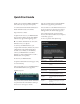
Quick CHAPTER Start Guide Thank you for purchasing a MOTU AVB interface! Follow these easy steps to get started quickly. ■ From your iPad or iPhone, launch the MOTU AVB Discovery app, and tap your interface. 1 Download and run the MOTU AVB Installer or MOTU AVB USB Installer.exe found here: ■ You should now see the MOTU AVB Control web app in your browser, as shown on page 14. If not, visit Appendix A, “Troubleshooting” (page 77). http://www.motu.
24Ai Front Panel 6 5 1 1. ANALOG INPUT METERS for the twenty-four analog inputs. 3. The CLOCK section displays the current operating sample rate and clock mode (source) for the unit. 2. ADAT OPTICAL input and output metering. At 1x sample rates (44.1 or 48 kHz), there are twenty-four channels of input and output. At 2x (88.2 or 96 kHz), there are twelve channels. 4. POWER SWITCH: AVB and USB are “plug-and-play” protocols.
24Ai Rear Panel 9 7 8 1 2 3 4 6 1. The 24Ai is equipped with an auto-switching international power supply. 2. BNC word clock jacks. Use them for a variety of applications, such as digital transfers with devices that cannot slave to the clock supplied by their digital I/O connection with the 24Ai. 3. These three ADAT optical “lightpipe” jacks provide 24 channels of 24-bit ADAT optical digital I/O at 1x sample rates (44.1 or 48 kHz) and 12 channels at 2x sample rates (88.2 or 96 kHz).
24Ao Front Panel 6 5 1 1. ANALOG OUTPUT METERS for the twenty-four analog outputs. 3. The CLOCK section displays the current operating sample rate and clock mode (source) for the unit. 2. ADAT OPTICAL input and output metering. At 1x sample rates (44.1 or 48 kHz), there are twenty-four channels of input and output. At 2x (88.2 or 96 kHz), there are twelve channels. 4. POWER SWITCH: AVB and USB are “plug-and-play” protocols.
24Ao Rear Panel 9 7 8 1 2 3 4 6 1. The 24Ao is equipped with an auto-switching international power supply. 2. BNC word clock jacks. Use them for a variety of applications, such as digital transfers with devices that cannot slave to the clock supplied by their digital I/O connection with the 24Ao. 3. These three ADAT optical “lightpipe” jacks provide 24 channels of 24-bit ADAT optical digital I/O at 1x sample rates (44.1 or 48 kHz) and 12 channels at 2x sample rates (88.2 or 96 kHz).
MOTU AVB Control Web App CHAPTER OVERVIEW MOTU AVB Control is a web app that gives you complete control over your MOTU audio interface. If you have several MOTU AVB interfaces networked together, such as the 24Ai, 24Ao and 8M, you can control them all. If you are working with a large-scale network of many MOTU AVB interfaces, you can access and control any device on the network.
DEVICE TAB 6 7 8 9 10 11 5 4 3 2 12 13 14 15 16 1 17 18 1. If you have two or more MOTU AVB interfaces, the Device list lets you choose the one you are currently controlling with the web app. 2. The Aux Mixing tab lets you view each Aux bus in the mixer, one at a time. 3. The Mixing tab gives you access to the mixing and DSP in the interface. 4.
DEVICE TAB (CONTINUED) 20 19 18 25 21 24 23 22 Scroll down to view these additional Device tab settings. 18. In the Input/Output Banks sections, you can disable any banks that you are not using. Doing so hides them from the routing matrix and mixer to simplify operation. Doing so also helps conserve DSP resources. 19. AVB is IEEE’s Audio Video Bridging Ethernet standard for highbandwidth, low-latency audio streaming over Ethernet.
ROUTING TAB 4 5 6 7 8 9 10 3 11 2 12 13 1 14 20 15 19 18 17 16 The Routing Tab lets you route inputs to outputs. Outputs are listed by row on the left; inputs are listed in columns across the top. Simply click in the grid to make a single connection. Click and drag to make multiple connections in one gesture. To route a single input to multiple outputs, make multiple connections vertically in the same column below the input.
MIXING TAB 3 4 5 6 7 8 9 10 11 12 13 14 15 16 2 17 1 30 18 29 28 19 20 27 21 26 22 23 24 25 The Mixing tab gives you full access to the 48-channel mixer in your MOTU AVB interface, which provides a main mix bus, monitor bus, three group busses, seven aux busses, and a dedicated reverb bus. Use the Device tab to configure how many inputs you wish to work with (up to 48). Use the Routing tab (page 16) to route channels to the mixer inputs.
AUX MIXING TAB 3 4 5 6 7 8 9 10 2 1 16 11 15 12 14 13 The Aux Mixing tab provides quick access to your MOTU AVB interface’s mix busses (aux busses, groups and reverb bus), viewed one at a time. Choose a bus in the Aux Mix Target section and then use the faders to directly mix the send levels from all mixer inputs, groups, and the reverb bus. 1. Shows and hides the Mixer Setup sidebar (3), which lets you show and hide channels. 2.
MIXER INPUT CHANNEL STRIPS 1 2 4 5 To access a mixer input channel strip, go to the Mixing tab (page 17), reveal the side bar (item #3 on page 17), and then show the input channel you want in the Mixer Inputs section (29). 26 6 7 3 25 3 8 To show and hide sections of the channel strip, such as EQ or the compressor, use the Controls section of the side bar (item #3 in the Mixing tab on page 17). 9 1. Click the input channel name to change it. Delete the current name to restore the default name. 2.
MAIN MIX AND MONITOR CHANNEL STRIPS 1 2 3 3 14 4 5 6 4 5 7 To access the Main Mix and Monitor channel strips, go to the Mixing tab (page 17) and scroll the display to the right, beyond the inputs and groups. To show and hide sections of the channel strip, such as EQ or the Leveler, use the Controls section of the side bar (item #3 in the Mixing tab on page 17). 8 1. By default, the Monitor bus serves as a solo bus.
AUX BUS CHANNEL STRIPS 1 2 10 3 Aux busses can be used to create sub-mixes. An aux bus can be assigned to any output in the Routing grid (page 16). 4 9 To access an Aux bus channel strip, go to the Mixing tab (page 17), reveal the side bar (item #3 on page 17), and then show the aux busses you want in the Mixer Outputs section (26). To show and hide the four-band EQ section of the channel strip, use the Controls section of the side bar (item #3 in the Mixing tab on page 17). 1. A stereo aux bus. 2.
GROUP AND REVERB CHANNEL STRIPS 1 9 2 3 Group busses can be used to create a mix subgroup, which is a set of inputs you wish to control together as a group. Groups differ from aux busses in that they have aux sends, a reverb send, as well as a main mix send. In addition, group busses are equipped with the Leveler. 4 The Reverb bus is a special group bus that provides a reverb processor. If you disable the reverb, the reverb bus functions as a (fourth) regular group bus.
CHAPTER 1 About Your MOTU AVB Audio Interface The 24Ai and 24Ao are hybrid USB2/AVB audio interfaces with 48-channel digital mixers and AVB Ethernet networking capability. They can operate as audio interfaces for a computer, as stand-alone digital mixers, as gateways to an expanded studio system, as components of an extended AVB audio network, or as capable hybrid devices performing all of these roles simultaneously.
8M 50 simultaneous audio channels Connection Input Output Quarter-inch analog on bal/unbal TRS - 8 Mic/guitar inputs on combo XLR/TRS 8 - Headphone output - stereo ADAT optical digital (at 44.1 or 48 kHz) 16 16 Total 24 26 16A 64 simultaneous audio channels Connection Input Output Quarter-inch analog on bal/unbal TRS 16 16 ADAT optical digital (at 44.1 or 48 kHz) 16 16 Total 32 32 Universal connectivity The 24Ai and 24Ao can connect to a computer with high-speed USB 2.
channel, or network stream to any other output, computer, or network device. You can also mult any single input to unlimited multiple output destinations. 24 channels of network audio I/O for your host computer The 24Ai and 24Ao let you stream up to 24 audio channels in and out, simultaneously, through their USB connection to a host computer.
ABOUT YOUR MOTU AVB AUDIO INTERFACE
CHAPTER 2 Packing List and System Requirements PACKING LIST PLEASE REGISTER TODAY! Your MOTU interface ships with the items listed below. If any of these items are not present in the box when you first open it, please immediately contact your dealer or MOTU. Please register your MOTU interface today. There are two ways to register. ■ One audio interface ■ One USB cable ■ One power cord ■ One manual ■ Product registration card ■ Visit www.motu.
PACKING LIST AND SYSTEM REQUIREMENTS
CHAPTER 3 Software Installation OVERVIEW USB 2.0 class-compliant operation. . . . . . . . . . . . . . . . . . . Operation as an AVB Ethernet audio interface . . . . . . . Software installation. . . . . . . . . . . . . . . . . . . . . . . . . . . . . . . . . Audio drivers . . . . . . . . . . . . . . . . . . . . . . . . . . . . . . . . . . . . . . . . MOTU AVB Discovery app for Mac . . . . . . . . . . . . . . . . . . . MOTU AVB WebUI Setup for Windows . . . . . . . . . . . . . . .
Download and run the MOTU AVB Audio Installer To download the latest MOTU AVB audio installer for Mac or Windows, visit www.motu.com/avb. Follow the directions that the installer gives you. ☛ We recommend that you run the software installer before you connect your MOTU interface to your computer and power it on. This ensures that all driver components are properly installed in your system.
AUDIODESK WORKSTATION SOFTWARE AudioDesk is an advanced workstation software package that lets you record, edit, mix, process, bounce and master multi-track digital audio recording projects. Advanced features include realtime effects processing, recording, and much more. See the AudioDesk User Guide, available on your computer hard drive as a PDF document. Figure 3-3: AudioDesk.
SOFTWARE INSTALLATION
CHAPTER 4 Hardware Installation OVERVIEW USB AUDIO INTERFACE SETUP Rack installation and heat . . . . . . . . . . . . . . . . . . . . . . . . . . . 33 USB audio interface setup . . . . . . . . . . . . . . . . . . . . . . . . . . . 33 AVB Ethernet audio interface setup. . . . . . . . . . . . . . . . . . 34 Setup for two interfaces . . . . . . . . . . . . . . . . . . . . . . . . . . . . . 34 Setup for three to five interfaces. . . . . . . . . . . . . . . . . . . . . 35 Setup for a multi-switch network . .
AVB ETHERNET AUDIO INTERFACE SETUP SETUP FOR TWO INTERFACES OR Thunderbolt is available on other MOTU AVB-equipped interfaces, such as the 1248, 8M, 16A and 112D. Use this setup if you want to use the 24Ai or 24Ao as an AVB Ethernet audio interface for a recentgeneration Mac (i.e. any Mac with a Thunderbolt port on it). Mac OS X Yosemite (10.10) or later is also required for AVB audio I/O. ■ Use a standard CAT-5e or CAT-6 cable. ■ Connect to the computer’s Ethernet port.
SETUP FOR THREE TO FIVE INTERFACES Use this setup if you want to connect three to five MOTU interfaces to your computer using a MOTU AVB Switch™ (sold separately). ■ The connection to the computer can be USB or Thunderbolt (if you have a Thunderbolt-equipped MOTU AVB interface). Use Thunderbolt, if possible, to support a large number of audio streams to and from the networked interfaces. A single Thunderbolt connection supports 128 channels in and out, simultaneously.
SETUP FOR A MULTI-SWITCH NETWORK ■ You can daisy-chain switches in serial fashion, but don’t create loops. For example, switches A, B, and C below are chained properly, but don’t connect C back to A. Alternately, you could connect both Switches B and C to Switch A. Use this setup if you want to connect more than five MOTU interfaces to an extended network that employs multiple AVB switches. AVB Ethernet is an industry standard, so you can use MOTU AVB Switches or 3rd-party AVB switches.
SETUP FOR MULTIPLE INTERFACES It is possible to connect multiple MOTU interfaces directly to your host computer through multiple USB (and Thunderbolt) ports. Alternately, you can connect multiple interfaces, operating as AVB Ethernet audio interfaces, using an AVB switch connected directly to the Mac.
SETUP FOR WEB APP CONTROL The MOTU AVB Control web app gives you access to all settings, routing, mixing, and effects processing in your audio interface, and each interface on the AVB network, if applicable. For more info, see “MOTU AVB Control Web App” on page 13. The web app is a web application served by the hardware. All you need to run it is a web browser running on a device that has a connection to your audio interface through USB or a shared network.
Ethernet cable A simple Ethernet cable connection can be used for web app control, even without a USB or Thunderbolt connection to your computer. For example, if you are using your MOTU device as a mixer or audio router, you could control the on-board routing, mixing and effects from the web app through a standard Ethernet connection. WiFi When using standard WiFi as shown, you can control your MOTU interface from multiple WiFi devices simultaneously.
AUDIO CONNECTIONS Here are a few things to keep in mind as you are making audio connections to your 24Ai or 24Ao interface. D-Sub connectors The 24Ai and 24Ao D-Sub connectors accept standard, female Panasonic/Tascam (AES-59) D-sub cables. Be sure the screws have standard 4-40 threading (not metric threading). For details and pin-outs, see Appendix D, “D-sub Connector Specifications” page (85). Analog trims All quarter-inch analog inputs and outputs can be trimmed.
Be sure to choose a digital audio clock master When you transfer digital audio between two devices, their audio clocks must be in phase with one another — or phase-locked. Otherwise, you’ll hear clicks, pops, and distortion in the audio — or perhaps no audio at all. Not phase-locked Phase-locked Device A C. Resolve both devices to a word clock source For A, choose Internal (or anything other than Optical) as the clock mode in the Device tab (item #13 on page 14).
Audio clock Master 2 In the device list (item #1 on page 14), choose the MOTU interface you wish to use as the clock master. Word clock master device Word clock OUT 3 Click the Become Clock Master button below the Clock Mode menu. Word clock IN Slave 24Ai Figure 4-9: Slaving your MOTU device (a 24Ai in this example) to word clock. For the 24Ai clock source, choose ‘Word Clock In’. Now, all other MOTU AVB devices on the network are resolved to this device.
SYNCING MULTIPLE AVB AUDIO INTERFACES CONNECTED TO A MAC There are several options for clocking multiple AVB audio devices connected to the Mac: ■ You can resolve them to an external clock source (like word clock, if available). ■ You can create an aggregate device, as usual. The aggregate device setup panel has a check box called Drift Correction, which sample-rate converts devices that are not synchronized.
HARDWARE INSTALLATION
Part 2 Using your MOTU interface
CHAPTER 5 Presets OVERVIEW AUDIO INTERFACE Because of its advanced, extensive feature set, your MOTU AVB interface can be used for many different purposes. This chapter discusses common use cases and their corresponding device presets, to help you use the hardware for your needs. Choose the Audio Interface preset to use your MOTU AVB device as a standard USB audio interface. Hardware inputs and outputs are accessible from your computer, and the mixer and audio networking features are disabled.
STAND-ALONE MIXER INTERFACE + MIXER Choose the Stand-alone mixer preset to use your MOTU AVB device as a mixer. Doing so routes all physical inputs to the mixer with the mixer main out and monitor out going to two hardware output pairs. Choose the Interface + Mixer preset to use your MOTU AVB device as both an audio interface and mixer, simultaneously. Doing so routes all physical inputs and outputs to and from the computer, connected through USB.
LIVE RECORDING WITH MONITOR MIXING Choose the Live recording with monitor mixing preset when you are tracking in the studio. The setup is pretty much the same as for the “Interface + mixer” preset discussed in the previous section, shown in Figure 5-3 on page 48. All physical inputs on the interface are routed to both the computer (for recording) and the Main Mix and Monitor busses in the mixer (for near-zero latency monitoring).
Stage I/O to network As another example, you could run an Ethernet cable from the stage unit to a MOTU AVB Switch, with a host of other MOTU AVB interfaces and computers on a multi-device network. Audio inputs from musicians on stage STUDIO INPUT EXPANDER Use the Studio Input Expander preset when you already have a main system set up, but you want to add additional inputs. This preset routes all physical inputs (analog and digital) on the expansion MOTU AVB interface to AVB network streams.
OPTICAL CONVERTER Choose the Optical converter preset if you would like your MOTU AVB device to serve as a multichannel analog-to-digital or digital-to-analog converter connected to another device equipped with an ADAT optical port. For example, if you have a 24Ai, you could connect the 24Ai optical output to the optical input on another device. The 24Ai then serves as a multichannel expander that adds an additional 24 analog inputs to your setup.
PRESETS
CHAPTER 6 The Front Panel LCD OVERVIEW LEVEL METERS The front panel LCD displays level meters for all inputs and outputs. The LCD also provides several navigable menus that provide status information and basic hardware settings. In its default state when the unit is first powered on, the LCD displays level meter activity for all physical audio inputs and outputs on the device. Level meters . . . . . . . . . . . . . . . . . . . . . . . . . . . . . . . . . . . . . . . . . ID button . . . . . . . . . . .
Device menu The Device menu provides information about the device, such as its name and connection mode (USB or AVB). Version menu The Version menu displays firmware version information. CLOCK Network menu The Network menu displays the following network-related information: Setting Explanation Serial/UID Unique AVB network identifier that can be used for troubleshooting. IP address The unique network address for the unit.
CHAPTER 7 Working with Host Audio Software OVERVIEW RUN THE WEB APP Your MOTU interface provides multi-channel audio input and output for Core Audio compatible audio applications on the Mac and ASIO or Wave compatible applications on Windows, including MOTU’s Digital Performer and AudioDesk, Apple’s Logic Pro and GarageBand, and other third-party software applications such as Ableton Live, Avid Pro Tools, Cockos Reaper, Propellerhead Reason and Record, Steinberg Cubase and Nuendo, Cakewalk SONAR, PreSon
Specifying the number of computer channels In the web app Device tab (page 15), in the Computer Setup section, specify the number of computer channels for streaming audio to and from your host audio software. You might want enough channels to cover the following: ■ Physical inputs you want to record on your computer. The physical outputs you want to send audio playback to.
Naming computer input and output channels Click on any computer input or output name in the routing grid (Figure 7-1) to change its name. computer channel row. Now, the mix bus output will be routed to the computer via the channel you selected. Streaming computer audio to and from the on-board mixer In Figure 7-1, you’ll see “mix” inputs across the top of the grid (Main, Monitor, Aux, etc.) These are output busses from the your interface’s on-board mixer.
Working with AVB network streams Audio channels going to networked AVB interfaces can be streamed to and from your host audio software through the MOTU interface connected directly to the computer. For information about how to set this up, see “Mapping computer channels to network streams” on page 73. Mirroring computer channels to multiple outputs Figure 7-1 shows an example of mirroring one stereo audio stream from your host audio software to several outputs.
REDUCING MONITORING LATENCY Monitoring latency is a slight delay caused by running an input signal through your host audio software and back out. For example, you might hear it when you drive a live guitar input signal through an amp modeling plug-in running in your audio sequencer.
☛ It is important to note that monitoring delay has no effect on the recording, or playback, of audio data from disk. The actual recording and playback is extremely precise, it is only the monitoring of your live input signal which may be delayed. Adjusting your host software audio buffer Buffers are small bundles of audio data. Your interface “speaks” to your computer in buffers, rather than one sample at a time.
Lower latency versus higher CPU overhead Buffer size has a large impact on the following: ■ Monitoring latency ■ The load on your computer’s CPU ■ Responsiveness of transport controls and effect knobs in AudioDesk, Digital Performer or other audio software. ■ Real-time virtual instrument latency. The buffer setting presents you with a trade-off between the processing power of your computer and the delay of live audio as it is being patched through your software.
WORKING WITH HOST AUDIO SOFTWARE
CHAPTER 8 Mixer Effects OVERVIEW Leveler . . . . . . . . . . . . . . . . . . . . . . . . . . . . . . . . . . . . . . . . . . . . . . . 66 This chapter provides further information about the effects processors available in the DSP mixer in your MOTU AVB interface. For basic mixer operation, see: The Leveler™, an accurate model of the legendary LA-2A optical compressor, which provides vintage, musical automatic gain control Reverb . . . . . . . . . . . . . . . . . . . . . . . . . . . . . . . . . . . . .
GATE All input channel strips provide a Gate module. Enabling EQ Each band has an enable/disable button (Figure 8-3), allowing you to enable as few or as many bands as needed for the channel strip. Figure 8-2: The Gate module. The gate silences the signal when the input signal’s level drops below the Threshold. Enable/disable The rate at which the gate responds, (opens to let signal through) is determined by the Attack parameter.
be flexible enough to cover a broad range of applications. By adjusting Gain and Bandwidth together, you can emulate the smooth and musical character of classic analog EQ circuits, in which the Gain/Bandwidth dependency was dictated by the actual circuit design and electrical components used. Low and high shelf filters The Low and High bands offer a shelf option that is similar to those found in most conventional parametric EQs. COMPRESSOR All mixer input channel strips provide a compressor module.
LEVELER The Leveler™ (Figure 8-5) provides an accurate model of the legendary Teletronix™ LA-2A® optical compressor, known for its unique and highly sought-after Automatic Gain Control (AGC) characteristics. Figure 8-5: The Leveler module. The Leveler is available on the Main Mix bus and all Group busses, including the Reverb bus. A model of an optical compressor An optical leveling amplifier works by shining a light on a photoresistor.
Enabling or disabling the Leveler The Leveler models the LA-2A so closely, it also models the time it takes for an actual LA-2A to “warm up” after it is turned on. Therefore, when you enable the Leveler, give it a moment to “settle” before you begin processing signals with it. Gain Reduction Gain Reduction (Figure 8-5) sets the strength of the signal sent to the AGC model. Makeup Gain Makeup gain (Figure 8-5) amplifies the output signal to make up for gain reduction.
setting represents the bottom frequency of the Mid band. The Ratio determines the length for each band specified in a percentage of the low frequency reverb time. DSP USAGE The DSP Usage meter (item #26 on page 19) shows how much of the available DSP processing power is currently being used by the mixer for the mix and for effects processing. If there aren’t enough DSP resources for all effects to be enabled on a channel, effects are disabled for that channel and all subsequent channels.
CHAPTER 9 Networking OVERVIEW The Audio Video Bridging (AVB) network port on your MOTU interface opens up a world of possibilities for creating expanded, customized audio network systems. About AVB . . . . . . . . . . . . . . . . . . . . . . . . . . . . . . . . . . . . . . . . . . . MOTU’s AVB implementation . . . . . . . . . . . . . . . . . . . . . . . . Networking examples . . . . . . . . . . . . . . . . . . . . . . . . . . . . . . . A quick guide to networking . . . . . . . . . . . . . . . . . . . . .
■ AVB is already shipping on current Macs — Apple supports AVB on all current shipping Macs, and the 24Ai and 24Ao can operate as a standard AVB audio interface when connected to your Mac’s AVB-equipped Ethernet port. MOTU’S AVB IMPLEMENTATION MOTU engineering has faithfully implemented the IEEE 802.1 AVB standard for the MOTU AVB products. This means that MOTU devices are fully interoperable with any 3rd party AVB-compatible device.
computer system. Despite the distance, the two interfaces operate as a seamless system, controlled from your computer or iPad. can stream audio anywhere on the network with near-zero latency, as if any two devices were connected directly to each other. Studio installation A studio installation of three to five interfaces can be handled with a single MOTU AVB Switch. See “Setup for three to five interfaces” on page 35.
millisecond latency through as many as seven switches. Audio can be distributed from a centralized location to anywhere in the venue. MOTU AVB interfaces or other AVB switches WiFi router, Ethernet hub/network, or computer A QUICK GUIDE TO NETWORKING MOTU AVB networking has been designed to be powerful, yet straightforward to set up and use. Here are a few things that are useful to know. Networking basics ■ Before proceeding below, review the networking connection diagrams on pages 34-36.
■ To add computers to the network, connect them to any interface using Thunderbolt (which offers the highest possible channel counts). If Thunderbolt is not available, use USB. ■ A computer can be connected to the network through its Ethernet port, but only for the purposes of running the web app on the computer for command and control over the network. (In this scenario, you won’t be able to stream audio to/from the network from the computer.
BRIDGING TO ETHERNET The Ethernet port on the MOTU AVB Switch allows you to connect standard network devices, such as: ■ A WiFi router ■ An Ethernet hub or switch connected to a local home, studio, or office network ■ Any other standard networking device THE MOTU AVB SWITCH The heart of a MOTU AVB network is the MOTU AVB Switch (sold separately). For a brief overview of the switch and its features, visit: www.motu.com/products/avb/avb-switch.
Part 3 Appendices
APPENDIX A Troubleshooting Some or all of my MOTU interface inputs and outputs are not available in my host audio software. Make sure that the inputs and outputs are enabled in the Device tab (“Device tab” on page 14) and routed to and from the computer in the Routing tab (“Routing tab” on page 16). For details, see “Making inputs and outputs available to your host software” on page 56. I have absolutely no audio input or output happening to or from my interface.
I hear clicks and pops under word clock sync. Many problems result from incorrect word clocking. It is essential that all digital devices in the system be word locked. Consult “Synchronization” on page 40 for detailed information on how to word clock your gear. Whenever there is any unexpected noise or distortion, suspect incorrect word lock. Clicks and pops due to hard drive problems...
APPENDIX B Audio Specifications 24Ao Line Out Connector Type Panasonic/Tascam format “DB-25” D-Sub AES-59 pin-outs, 4-40 retaining screw Phoenix screw block Pin-outs as indicated by connector labeling Output Impedance 100 ohm Per leg Dynamic Range 123 dB A-weighted THD+N -110 dB (0.0003%) -1 dBFS, Unweighted, 1 kHz Frequency Response +0, -0.1 dB, 20 Hz/20 kHz Ref.
24Ai Line In Connector Type Specification Panasonic/Tascam format “DB-25” D-Sub AES-59 pin-outs, 4-40 retaining screw Phoenix screw block Pin-outs as indicated by connector labeling Complies with EBU-R68 / SMPTE RP-155 Impedance Load 10 k ohm Dynamic Range 110 dB A-weighted THD+N -102 dB (0.0008%) -1 dBFS, Unweighted Frequency Response +0, -0.1 dB, 20 Hz/20 kHz Ref.
APPENDIX C Mixer Schematics MONO INPUT CHANNEL 81
STEREO INPUT CHANNEL + 82 APPENDIX C: MIXER SCHEMATICS
GROUP BUS + 83 APPENDIX C: MIXER SCHEMATICS
MONITOR BUS + 84 APPENDIX C: MIXER SCHEMATICS
APPENDIX D D-sub Connector Specifications D-SUB CABLE PIN-OUTS The 24Ai and 24Ao follow the Panasonic/Tascam (AES-59) standard specification for a female D-sub connector with balanced analog input or output. A NOTE ABOUT RETAINING SCREWS The 24Ai and 24Ao D-sub connectors are equipped with standard nuts with a 4-40 thread size, which support 4-40 retaining screws. When you purchase your DB-25 cable, most DB-25 cables include 4-40 screws, but they may not be installed on the cable yet.
APPENDIX D: D-SUB CONNECTOR SPECIFICATIONS
APPENDIX E Updating Firmware MOTU periodically posts firmware updates for your MOTU AVB interface. These updates may include bug fixes, enhancements, and new features. Updates are posted on MOTU’s servers. If your computer or Wi-Fi device has access to the internet, the MOTU AVB Control app notifies you as soon as an update is made available. Otherwise, you can check motu.com/avb periodically for the latest firmware update.
Updating off-line, without internet access If your MOTU AVB interface (and the computer it is connected to) has no internet access, you can download a firmware update file from another computer that does have internet, and then use the file to update your MOTU interface, as follows: 1 Download the firmware file. 2 Transfer the file to a computer with a network cable connection to your MOTU interface. 3 Launch the MOTU AVB Control web app on the computer, as usual. 4 Go to the Device tab.
APPENDIX F OSC Support Open Sound Control (OSC) is a protocol for communication among computers and other multimedia devices that is optimized for modern networking technology. MOTU AVB audio interfaces support OSC, which provides remote control of all device settings and mixer controls from any OSC-enabled controller. For further details about remote control through OSC, along with complete documentation for the MOTU AVB OSC API, visit: http://www.motu.
APPENDIX F: OSC SUPPORT
Index 24Ai expansion 34 front panel 9 installing 33 rear panel 10 summary of features 23 24Ao expansion 34 front panel 11 installing 33 rear panel 12 summary of features 23 24-bit optical 10, 12 2x SMUX mode 15, 40 A Ableton Live 55, 58 ADAT optical 10, 12 connecting 40 SMUX Type 54 Analog inputs/outputs 40 Apple Garage Band 58 Logic Pro 58 ASIO Buffer Size 30 ASIO monitoring 59 Attack Compressor 64, 65 Audio interface preset 7, 47 AudioDesk 25, 31, 55, 58 authenticating 77 Aux Mix Target 18 Aux Mixing tab
stand-alone operation 63 Mixing tab 17 MOTU AudioDesk 58 AVB Control web app 7, 13-22 Aux Mixing tab 18 Device tab 14, 15 Mixing tab 17 Routing tab 16 AVB Discovery app 7, 30 AVB Installer 7, 29 AVB Switch setup 35, 39 Digital Performer 58 MOTU AVB Control web app 13 Discovery app 13 Installer 13 USB ASIO driver 58 WebUI Setup 13 MOTU AVB WebUI Setup 30 N Networking 69-74 installation 35, 36 Nuendo 55, 58 clock source 55 sample rate 55 O Optical 2x mode 54 connectors 10, 12, 40 S/PDIF 40 Optical converter