
User Manual


MOTU AVB CONTROL WEB APP
16
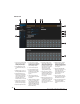
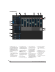
ROUTING TAB
54 7
11
3
2
12
14
The Routing Tab lets you route inputs to
outputs. Outputs are listed by row on the
left; inputs are listed in columns across
the top. Simply click in the grid to make
a single connection. Click and drag to
make multiple connections in one
gesture. To route a single input to multi-
ple outputs, make multiple connections
vertically in the same column below the
input. To mix multiple inputs to the
same output, you’ll need to use the
mixer (page 17) and the
Mix In
bank in
the routing tab (16).
1. In its collapsed form, (shown here),
the sidebar displays icons for each
tab.
2. Click this icon to view the Routing
tab, shown on this page.
3. Click here to show or hide the
sidebar.
4. Create, save, recall and manage
routing presets.
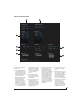
5. Outputs are listed in rows on the left.
6. When you make a connection, the
source (input) signal is listed by
name here in the Source column,
just to the right of the output it is
being routed to.
7. Inputs are listed in columns across
the top of the grid, starting with the
physical inputs on the hardware
itself. In this example, each
8-channel ADAT optical bank is
collapsed. In the grid below, in the
first column, you can see that Bank A
input is routed to the computer.
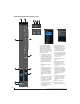
8. The
From Computer
input bank lets
you route audio channels from your
host audio software to any output,
including AVB network streams or
the mixer. In this example, all 24
computer output channels are
routed to the 24Ao analog outs. Use
the Device tab to choose how many
computer channels are available.
9. AVB streams are 8-channel banks
that let you route audio to or from
other devices on the AVB network (if
any are connected) to local
hardware inputs and outputs. Use
the Device tab (page 15) to config-
ure how many AVB streams you wish
to work with. If you aren’t working
with network audio, you can set the
number of streams to zero.
10. These input streams are busses that
originate from the mixer, which
supplies the main mix bus, monitor
mix bus, seven stereo aux busses,
three stereo group busses, a reverb
return bus and postFX channel sends
(for sending processed inputs to the
computer or elsewhere). You can
route these mixer busses to any
outputs you wish (5), including
physical outputs, host software on
your computer, other devices on the
AVB network, or even back in to the
mixer (beware of feedback loops!)
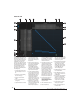
11. Use these triangles to expand or
collapse groups of inputs. For
example, it might be convenient to
collapse banks that you are not
using at the moment.
12. Click a channel label to rename it.
13. Audio activity indicators.
14. Click the grid to make a connection.
Click a connection to remove it. Click
and drag to make or break multiple
connections in one gesture.
15. In this example, all 24 channels from
the computer are routed to the 24
analog outputs on the 24Ao. In
addition, all 24 computer channels
are simultaneously being routed to
the three ADAT banks, for 24
channels of digital output.
16. The
Mix In
group lets you route audio
to the 48-channel mixer.
17. These AVB output streams let you
route any audio to other devices on
the AVB network.
18. The
To Computer
output bank routes
any input to host audio software
running on your computer. Use the
Device tab to choose how many
computer channels are available.
19. Use these triangles to expand or
collapse groups of outputs.
20. These are the physical outputs on
the interface itself.
1
6
15
8 9
10
13
19
20
16
17
18