
User Manual


MOTU AVB CONTROL WEB APP
19
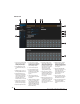
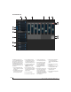
MIXER INPUT CHANNEL STRIPS
1
6
To access a mixer input channel strip, go
to the Mixing tab (page 17), reveal the
side bar (item #3 on page 17), and then
show the input channel you want in the
Mixer Inputs
section (29).
To show and hide sections of the channel
strip, such as EQ or the compressor, use
the
Controls
section of the side bar (item
#3 in the Mixing tab on page 17).
1. Click the input channel name to
change it. Delete the current name to
restore the default name.
2. Provides hardware settings for
inputs, if any, on other MOTU AVB
interfaces. In the case of the 24Ai and
24Ao, this is grayed out because there
are no hardware settings for inputs.
3. Choose the source for the input
channel. You can also make this
setting directly on the Routing grid
(page 16).
4. Create, name, save and recall channel
strip presets.
5. Toggles the input between mono and
a stereo pair.
6. High Pass Filter with cutoff frequency.
7. Each effect in the channel strip (High
Pass Filter, Gate, EQ, etc.) has an on/
off button (on the left) and a preset
menu on the right, for managing
presets that apply only to that
processing module. For example, you
can create your own EQ presets for the
EQ modules.
8. The Gate processor provides standard
attack, threshold and release
controls.
9. The Gate indicator turns red when the
gate is engaged.
10. The EQ section provides four bands of
parametric EQ, each with standard
Gain, Frequency, and Bandwidth
settings.
11. The High and Low EQ bands provide a
Shelf
filter button for standard high
and low shelf filtering.
12. The Compressor provides standard
controls for Threshold, Ratio, Attack,
Release and Gain. Normally, the
compressor operates in Peak mode,
where signal peaks determine the
input level. Engage the RMS button to
uses RMS values (a computational
method for determining overall
loudness) to measure the input level.
13. Input level and gain reduction meters
for the compressor.
14. Aux and reverb sends.
15. Solo/Mute. Mute affects all sends as
well as the main channel. Pre-fader
sends are not affected by Mute.
16. Move the fader to adjust level.
Double-click to return to zero (unity
gain) or -
∞
.
17. Click the dB scale numbers to make
the fader jump exactly to that level.
Click and drag horizontally to jump
consecutive faders to the same level.
18. Click to type in an exact dB level.
19. Channel pan. For mono inputs,
double-click to center.
20. Main Mix Slider is used to feed signal
to the Main Mix. Slider is set to 0 dB
by default, so all channel strips are
pre-routed to the Main Mix bus. If a
channel is being sent to a Group
(which will eventually be fed to the
Main Mix), drag the slider to -
∞
so it
is not sent to Main Mix directly.
21. Group sends.
22. ‘S’ lets you solo the group. ‘PRE’
toggles the sends between pre- and
post-fader routing, i.e. before or after
the channel fader.
23. Clears all solos.
24. ‘S’ lets you solo the Aux bus. ‘PRE’
toggles the sends between pre- and
post-fader routing, i.e. before or after
the channel fader. The dots let you
toggle the Aux bus between mono
and stereo.
25. This side bar, with the section labels
in it, can be shown or hidden using
the
Legend
switch in the
Controls
section of the side bar (item #3 in the
Mixing tab on page 17).
26. Shows how much DSP power is being
used by the mixer hardware. To free
up DSP bandwidth, try reducing the
number of mixer ins, disabling
channel effects, reverb, etc. See “DSP
Usage” on page 68 for more info.
26
25
23
24
2 3 4 5
7
22
9
8
10
11
12
13
14
15
16
17
18
19
21
3
4
20