Track16 ™ User Guide for Windows 1280 Massachusetts Avenue Cambridge, MA 02138 Business voice: (617) 576-2760 Business fax: (617) 576-3609 Web site: www.motu.com Tech support: www.motu.
About the Mark of the Unicorn License Agreement and Limited Warranty on Software TO PERSONS WHO PURCHASE OR USE THIS PRODUCT: carefully read all the terms and conditions of the “click-wrap” license agreement presented to you when you install the software. Using the software or this documentation indicates your acceptance of the terms and conditions of that license agreement. Mark of the Unicorn, Inc. (“MOTU”) owns both this program and its documentation.
Contents Part 1: Getting Started 7 Quick Reference: Track16 Operation 8 Quick Reference: Track16 Connectors 9 Quick Reference: MOTU Audio Console 11 About the Track16 17 Packing List and System Requirements 19 Installing the Track16 Software 21 Installing the Track16 Hardware Part 2: Using Track16 33 MOTU Audio Console 39 Hardware operation 41 Configuring Host Audio Software 49 Reducing Monitoring Latency 55 CueMix FX 101 MOTU SMPTE Console Part 3: Appendices 107 Audio I/O referen
Part 1 Getting Started
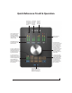
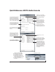
Quick Reference: Track16 Operation CHAPTER Level meters for the two mic inputs or the eighth-inch stereo mini jack on the front. Level meters for the two guitar inputs or the phone jacks on the front. Level meters for the line inputs or the line outputs. These 7-segment level meters have a range from -42 dB to -1 dB. The top red LED illuminates when the signal reaches 1 dB below full scale — for even just one sample. Dedicated level meters for the main outs.
Quick Reference: Track16 Connectors 1 Guitar 1 2 Line In 3-4 3 4 Phones 6 DB25 Breakout cable 7 Optical I/O 8 9 10 11 12 13 14 Mic inputs 1-2 MIDI IN/OUT Guitar 2 Line In 1-2 Main out 1-2 Line out 1-2 DC Power (14V) 1. This is one of two hi-Z guitar inputs. The second guitar input is on the breakout cable (10). 2. Line In 3-4 is a stereo eighth-inch “mini” jack for connecting an iPod or other mobile audio device. 3.
Quick Reference: MOTU Audio Console CHAPTER Click the tabs to access general MOTU interface settings or settings specific to the Track16 (or other connected interface.) Choosing a smaller setting here reduces the delay you may hear when listening to live input that you are running through effects plug-ins in your software. But lower settings also increase the strain on your computer. For details, see “Samples Per Buffer” on page 35.
CHAPTER 1 About the Track16 Overview . . . . . . . . . . . . . . . . . . . . . . . . . . . . . . . . . . . . . . . . . . . . The Track16 I/O connections. . . . . . . . . . . . . . . . . . . . . . . . . The Track16 Top panel . . . . . . . . . . . . . . . . . . . . . . . . . . . . . . . 16-bit and 24-bit recording . . . . . . . . . . . . . . . . . . . . . . . . . . CueMix FX 32-bit floating point mixing and effects. . Included software . . . . . . . . . . . . . . . . . . . . . . . . . . . . . . . . . . .
THE TRACK16 I/O CONNECTIONS The Track16 has the following I/O connections, supplied either on the base unit itself or on the included DB25 breakout cable. All Track16 inputs and outputs can be used simultaneously, for a total of 16 inputs and 16 outputs at 44.
dently, allowing you to mix and match any optical formats on input and output. For example, you could receive 4 channels of 96 kHz S/MUX input while at the same time sending 96 kHz stereo optical S/PDIF (“TOSLINK”) output. MIDI I/O The Track16’s standard MIDI IN and MIDI OUT jacks supply 16 channels of MIDI I/O to and from the computer. On-board SMPTE synchronization The Track16 can resolve directly to SMPTE time code via any analog line input, without a separate synchronizer.
analog or digital inputs and outputs. 24-bit audio files can be recorded with any compatible host application that supports 24-bit recording. CUEMIX FX 32-BIT FLOATING POINT MIXING AND EFFECTS All Track16 inputs and outputs can be routed to the on-board CueMix FX 8-bus (4 stereo) digital mixer driven by hardware-based DSP with 32-bit floating point precision.
CueMix FX provides many advanced features, such as an accurate instrument tuner and an extensive arsenal of audio analysis tools, including a realtime FFT, spectrogram “waterfall” display, oscilloscope, and phase analysis tools. HOST AUDIO SOFTWARE The Track16 system ships with Windows drivers that allows you to record, edit, play back and mix your Track16 projects using your favorite Windows audio software.
ABOUT THE TRACK16
CHAPTER 2 Packing List and System Requirements PACKING LIST PLEASE REGISTER TODAY! The Track16 ships with the items listed below. If any of these items are not present in your Track16 box when you first open it, please immediately contact your dealer or MOTU. Please register your Track16 today. There are two ways to register.
PACKING LIST AND SYSTEM REQUIREMENTS
CHAPTER 3 Installing the Track16 Software OVERVIEW 2 Power off and disconnect the Track16. Installation. . . . . . . . . . . . . . . . . . . . . . . . . . . . . . . . . . . . . . . . . . . MOTU Audio drivers . . . . . . . . . . . . . . . . . . . . . . . . . . . . . . . . . MOTU Audio Console . . . . . . . . . . . . . . . . . . . . . . . . . . . . . . . . MOTU MIDI Driver . . . . . . . . . . . . . . . . . . . . . . . . . . . . . . . . . . . CueMix FX . . . . . . . . . . . . . . . . . . . . . . . . . . .
MOTU AUDIO DRIVERS ASIO ASIO is an acronym for Audio Streaming Input and Output. The MOTU Audio ASIO driver provides multi-channel audio input and output for applications that support ASIO audio drivers, such as Ableton Live, Avid Pro Tools, Cakewalk SONAR, Cockos Reaper, Propellerhead Reason and Record, Steinberg Cubase and Nuendo, and others. For details about using the Track16 with ASIO, see chapter 7, “Configuring Host Audio Software” (page 41). WDM WDM is an acronym for Windows Driver Model.
CHAPTER 4 Installing the Track16 Hardware OVERVIEW Here’s an overview for installing the Track16: miniature Type A ports, use the appropriate 9-pinto-6-pin or 9-pin-to-4-pin FireWire cable (sold separately). Connect the Track16 interface . . . . . . . . . . . . . . . . . . . . . . . 21 Connect the Track16 to the computer. Connect audio inputs and outputs . . . . . . . . . . . . . . . . . . 23 Make optical and analog connections as desired. Connect MIDI gear. . . . . . . . . . . . . . . . . . . . . . .
3 Plug the other end of the FireWire cable into the Track16. ☛ Make absolute sure to align the notched side of the FireWire plug properly with the notched side of the FireWire socket on the Track16. If you attempt to force the plug into the socket the wrong way, you can damage the Track16. High Speed USB 2.0 versus USB 1.1 There are primarily two types of USB host controllers widely available on current personal computers. USB 1.
CONNECT AUDIO INPUTS AND OUTPUTS Track16 connectors are located on the front and rear of the base unit. The DB25 connector on the rear panel connects to the Track16’s included breakout cable, which provides further connections for audio, MIDI and power.
5 The red “V” LED illuminates (Figure 4-2). 6 To disable phantom power, simply repeat this procedure. The red “V” LED turns off. -20 dB pad If the input signal is too hot with the trim turned all the way down, engage the -20dB pad for the input. To toggle the pad, push the appropriate mic button and then quickly push the knob. The amber “P” LED will turn on or off accordingly. Muting mic inputs Mic inputs without a mic or terminator connected can pick up noise, so keep them muted when not in use.
Line input trims The line inputs are calibrated to accommodate either +4 dB or -10 dB signals and are equipped with digitally controlled analog trims that provide -96 dB of cut and +22 dB of gain. You can use either the main volume knob or the included CueMix FX software to adjust the input trim. To adjust these trims using CueMix FX, see “Input trim” on page 61. To adjust the trims using the volume knob: 1 Push the corresponding input button. 2 Turn the volume knob.
For details about using the clock source setting and the MOTU Audio Setup software in general, see chapter 5, “MOTU Audio Console” (page 33). to do this with devices that receive on only one MIDI channel (such as effects modules) so their receive channels don’t conflict with one another. CONNECT MIDI GEAR Connect your MIDI device’s MIDI IN jack to the Track16’s breakout cable MIDI OUT jack (Connection A below).
✓ ✗ YES NO 6-pin FireWire 4-pin FireWire Figure 4-6: 4-pin FireWire connectors cannot be used for bus power. When operating under bus power, daisy-chaining is not recommended The Track16 can be daisy-chained with other FireWire devices from a single FireWire connection to the computer. However, if the Track16 is operating under bus power, this is not recommended. If you need to daisy chain the Track16 with other devices on the same FireWire bus, power the Track16 with the included power adapter.
A TYPICAL TRACK16 SETUP Here is a typical Track16 studio setup. This rig can be operated without a conventional mixer. All mixing and processing can be done either in the Track16, in the computer with audio software, or both. During recording, you can use the Track16’s Secondary studio monitors Main studio monitors CueMix™ FX mixer to apply reverb, EQ and compression to what you are recording and monitor it via the main outs, headphone outs, or any other output pair.
CONNECTING MULTIPLE MOTU FIREWIRE INTERFACES You can daisy-chain up to three MOTU FireWire interfaces on a single FireWire bus, but do not run the Track16 or other bus-powered interfaces under bus power when doing so. When connecting multiple MOTU interfaces, MOTU Audio Console displays the settings for one interface at a time. To view the settings for an interface, click its tab.
INSTALLING THE TRACK16 HARDWARE
Part 2 Using Track16
CHAPTER 5 MOTU Audio Console OVERVIEW ACCESSING THE TRACK16 SETTINGS MOTU Audio Console gives you access to basic Track16 hardware settings, such as sample rate, clock source, optical format and more. There are several ways to access Track16 settings: Accessing the Track16 settings. . . . . . . . . . . . . . . . . . . . . . . ‘General’ tab settings . . . . . . . . . . . . . . . . . . . . . . . . . . . . . . . . Sample Rate . . . . . . . . . . . . . . . . . . . . . . . . . . . . . . . . . . . . . . . .
‘GENERAL’ TAB SETTINGS Sample Rate Choose the desired Sample Rate for recording and playback. The Track16 can operate at 44.1 (the standard rate for compact disc audio), 48, 88.2, 96, 176.4 or 192KHz. If you are operating at a sample rate between 44.1 and 96kHz, make absolutely sure that all of the devices connected digitally to the Track16’ optical connectors match the Track16’s sample rate. At the 4x sample rates (176.4 or 192kHz), optical I/O is disabled.
menu when the optical input bank is enabled and set to the ADAT Optical format, as explained in “Optical input/output” on page 36. This setting is useful if you just need to make a simple, click-free digital transfer between the Track16 and another device. Samples Per Buffer The Samples Per Buffer setting lets you reduce the delay you hear when patching live audio through your audio software.
effects, mixing and other real-time operations. But don’t set the Samples Per Buffer too low, or it may cause distortion in your audio. If you don’t process live inputs with software plug-ins, leave this setting at its default value of 1024 samples. If you do, try settings of 256 samples or less, if your computer seems to be able to handle them. If your host audio software has a processor meter, check it.
Return Assign The Return Assign menu lets you choose any pair of Track16 audio outputs. The audio signal from this output pair is then sent back to the computer via the Stereo Return 1-2 bus. This stereo return bus from the Track16 appears in your host software alongside all other Track16 inputs, wherever your host software lists them. The Track16 stereo return bus can be used for a variety of purposes.
MOTU AUDIO CONSOLE
CHAPTER 6 Hardware operation METERS The first time you switch on the Track16, its LED meters show signals indicated by the white labels below them. Push the METERs button to toggle the meters to display the signals indicated by the blue labels. The METERs button glows blue. Push it again to return to the white labels (dim blue). The buttons let you quickly choose what the knob does.
Output volume control To control volume, push the desired output (MAIN, PHONES, or LINE OUT). The button illuminates green. Turn the knob to adjust the output volume. Input trim To control input trim, push the desired input (MIC, GUITAR, or LINE IN). The button illuminates green. Turn the knob to adjust the input trim. Input bus volume To control input bus level (CueMix input fader), push the output bus (MAIN, PHONES, LINE OUT) and the desired input (MIC, GUITAR, or LINE IN) at the same time.
CHAPTER 7 Configuring Host Audio Software OVERVIEW The Track16 provides multi-channel audio input and output for ASIO- and WDM-compatible audio applications, including Ableton Live, Avid Pro Tools, Cockos Reaper, Propellerhead Reason and Record, Steinberg Cubase and Nuendo, Cakewalk SONAR, and others. and outputs will be available to your software, so this is an important step. For complete details see chapter 5, “MOTU Audio Console” (page 33).
If you are slaving the Track16 and your host software to SMPTE time code, follow the directions in chapter 10,“MOTU SMPTE Console” (page 101). ☛ In order to use the Track16’s direct SMPTE sync (and sample-accurate sync) feature, the host audio software must support the ASIO 2.0 sampleaccurate positioning protocol. Cubase and Nuendo support this protocol; for other software, check with its documentation.
CHOOSING THE MOTU AUDIO DRIVER Once you’ve made the preparations described so far in this chapter, you’re ready to run your audio software and enable the MOTU Audio driver. Check the audio system or audio hardware configuration window in your software. There will be a menu there that lets you choose among various drivers that may be in your system. Choose the desired MOTU Audio driver from this menu. Several driver options are available. For a summary, see “MOTU Audio drivers” on page 20.
Live In Ableton Live, access the preferences window and click the Audio tab. Choose ASIO from the Driver Type menu. Choose the MOTU Audio ASIO from the Input Audio Device and Output Audio Device menus as shown below in Figure 7-4. To enable or disable input or output channels, click the Input Config or Output Config buttons. Reaper In Cockos Reaper, access the Preferences and click Devices under the Audio preferences.
Figure 7-7: Enabling the MOTU Audio ASIO driver in SONAR. Figure 7-8: Enabling the MOTU WDM driver in SONAR. 4 Next, in the Audio preferences section, choose Devices. 4 Next, in the Audio preferences section, choose Devices. 5 Check the Track16 inputs and outputs that you wish to use and uncheck the ones you don’t. 5 Check the Track16 inputs and outputs that you wish to use and uncheck the ones you don’t, as shown in Figure 7-7 on page 45. Using the MOTU WDM driver 1 Go to SONAR’s Preferences.
REDUCING LATENCY On Windows, audio I/O buffer size is handled by the audio driver rather than the host audio application. In the MOTU Audio Console, Samples Per Buffer provides an adjustable audio buffer setting that lets you control the amount of delay you’ll hear when monitoring live inputs through your host audio software or processing them with software plug-ins. For information, see the “Adjusting the audio I/O buffer” section of chapter 8,“Reducing Monitoring Latency” (page 49).
Mix1 1-2 return bus In your host audio software audio input menus, you’ll see an Track16 input called Mix1 Return 1-2. This is a stereo feed from the Track16 that matches its main outs (Mix 1). This can be used, for example, to record a final stereo mix for reference and archiving purposes. ☛ Warning: the Mix1 Return 1-2 return inputs can cause feedback loops! DO NOT assign this input to a track assigned to the Track16 main outs.
CONFIGURING HOST AUDIO SOFTWARE
CHAPTER 8 Reducing Monitoring Latency OVERVIEW Monitoring latency is that slight delay you hear when you run an input signal through your host audio software. For example, you might hear it when you drive a live guitar input signal through an amp modeling plug-in running in your audio sequencer.
MONITORING LIVE INPUT There are two ways to monitor live audio input with an Track16: 1) through the computer or 2) via the Track16 CueMix FX hardware mixer. Figure 8-1 shows method 1, which allows you to apply host-based effects processing via plug-ins in your audio software. See the next section, “Adjusting the audio I/O buffer” for details about how to reduce — and possibly eliminate — the audible monitoring delay that the computer introduces.
ADJUSTING THE AUDIO I/O BUFFER A buffer is a small amount of computer memory used to hold data. For audio interfaces like the Track16, buffers are used for the process of transferring audio data in and out of the computer. The size of the buffers determines how much delay you hear when monitoring live inputs through your audio software: larger buffers produce more delay; smaller buffers produce less.
Lower latency versus higher CPU overhead The buffer setting has a large impact on the following things: ■ Patch thru latency ■ The load on your computer’s CPU ■ Possible distortion at the smallest settings ■ How responsive the transport controls are in your audio software The buffer setting presents you with a trade-off between the processing power of your computer and the delay of live audio as it is being patched through your software.
CueMix FX allows you to create up to eight separate Track16 stereo mixes, or any other desired routing configurations. These routings are independent of your host audio software. For complete details, see chapter 9, “CueMix FX” (page 55). Controlling CueMix FX from your audio software Some ASIO-compatible audio applications, such as Cubase and Nuendo, allow you to control CueMix FX monitoring from within the application (without the need to use CueMix FX).
REDUCING MONITORING LATENCY
CHAPTER 9 CueMix FX OVERVIEW A 16-BUS MIXER WITH EQ, COMPRESSION AND REVERB CueMix FX is a cross-platform software application that provides graphic, on-screen control for the Track16’s flexible CueMix FX on-board mixer and effects processing. All Track16 inputs can be routed to the on-board CueMix FX 16-bus (8 stereo bus) digital mixer driven by hardware-based DSP with 32-bit floating point precision. CueMix FX also provides many advanced audio analysis tools, including a tuner and oscilloscope.
ADVANTAGES OVER HOST-BASED MIXING AND PROCESSING CueMix FX provides several major advantages over mixing and processing in your host audio software: ■ CueMix has no buffer latency. Thanks to the Track16’s DSP chip, CueMix provides the same throughput performance as a digital mixer. ■ CueMix mixing and effects processing imposes no processor drain on the computer’s CPU. ■ CueMix routing can be maintained independently of individual software applications or projects.
Output channels The Outputs tab (Figure 9-6 on page 63) gives you access to settings for each Track16 output pair, including EQ, dynamics processing and send/ return controls for feeding and returning the output signal to/from the Track16’s global reverb processor. These settings are applied to the signal just before it is sent to the output.
THE MIXES TAB Click the Mixes tab (Figure 9-2) to gain access to the Track16’s eight stereo mix busses. The Mixes tab displays one mix bus at a time. Viewing a mix Choose the mix you wish to view from the mix bus menu (in the Mixes tab itself, as shown in Figure 9-2). The menu shows all mixes by name, followed by the Track16 output pair to which each bus master fader is assigned.
Bus reverb send/return The bus reverb send (Figure 9-2) feeds the output of the mix bus, pre-fader, to the Track16’s global reverb processor, where it is merged with any other signals being fed to the reverb. The reverb’s output can then be fed back into the mixer at various return points, including the bus return (discussed below). The bus reverb return (Figure 9-2) feeds the output of the Track16’s global reverb processor into the mix bus, pre-fader.
THE INPUTS TAB The Track16 provides many features for managing analog and digital input signals. Some of these features, such as the Track16’s digitally controlled analog trims, are implemented in the analog domain; others are implemented in the digital domain as DSP applied to the digital signal (after the A/D converter on analog inputs). Click the Inputs tab (Figure 9-3) to access and control all of these input channel settings for each Track16 input or input pair.
Input channel focus Click the channel focus button (Figure 9-3) to view and edit parameters in the channel settings section of the CueMix FX window (Figure 9-7 on page 64). Input EQ and dynamics The Track16 lets you apply 7-band parametric EQ and dynamics processing (DSP) to any input, analog or digital. Mono/stereo pairing Click the Mono button (Figure 9-3) if you would like an input to be treated as a mono channel.
Orange Green Blue Red Yellow White Black EQ band selectors LP/HP filter selector Compressor selector EQ/Dynamics enable/disable buttons Click the EQ or Dynamics button at the bottom of the input channel (Figure 9-3) to toggle the effect on or off. Note that you can program EQ and compressor settings, even when the effect is currently disabled. (You just won’t hear the result until you enable it.) Colored knobs Figure 9-4: The EQ/Dynamics selectors.
Output channel focus Click the channel focus button (Figure 9-6) to view and edit parameters in the channel settings section of the CueMix FX window (Figure 9-7 on page 64). Channel focus also determines which channels are being scoped by CueMix’s audio analysis tools, as explained in “Choosing channels for audio analysis” on page 80. Output EQ and Dynamics The EQ/Dynamics section in the Outputs tab (Figure 9-6) works identically to the EQ/Dynamics section for the Inputs tab (Figure 9-3).
THE CHANNEL SETTINGS SECTION The channel settings section in the CueMix FX window (Figure 9-1) displays three tabs for Channel, EQ and Dynamics settings for the channel with the current focus. There are also two global tabs: the Meter Bridge and the Reverb Processor, as shown below. The Channel tab The Channel tab (Figure 9-8) displays settings for input channels. Click any focus button in the Inputs tab to view the Channel tab settings for the channel. Figure 9-8: The Channel tab.
Stereo settings Inputs that have been grouped as stereo pairs in the Inputs tab (Figure 9-3) provide two stereo modes (Figure 9-8): Normal and M/S. M/S mode provides decoding for a mid-side microphone configuration. The Width knob (Figure 9-8) provides control over the stereo imaging, going from a full stereo image to mono (both channels panned equally). See “Width” on page 59. The Swap L/R button (Figure 9-8) lets you switch the left and right channels.
The EQ tab The EQ tab (Figure 9-10) displays the EQ settings for the input or output channel that currently has the focus. Click any focus button in the Inputs or Outputs tab to view the EQ tab settings for the channel. Vintage EQ Inspired by legendary British large console EQs, the Track16 Vintage EQ section (Figure 9-10) gives you the look, feel and sound of the most soughtafter classic equalizers.
Vintage EQ Quick reference Filter response display: Shows the response curve for the current settings. Composite curve (white line): shows the overall Vertical scale: Lets you zoom the vertical scale of Individual filter curve: Each filter has a color the filter response display. (indicated by its knobs). When filter curves are being displayed (the filter curve option is turned on), each individual filter’s response curve is displayed in the filter’s color.
Showing and hiding filter curves To view a filter in the display, turn on the filter. The shape of the filter, according to its current settings, is shaded in the same color as the filter’s knob(s). Use the filter display options menu (Figure 9-10) to show or hide them in the display.
Type I Type II Figure 9-13: Type I EQ filter style. Figure 9-14: Type II EQ filter style. The Type I EQ filter has the least amount of Gain/Q interaction, providing the most precision and control of all the EQ filter types. Even small adjustments in gain or reduction produce relatively high Q. This EQ style is best for situations that call for precise EQ adjustments requiring the maximum amount of individual parameter control. For more general shaping (e.g. full mixes) or subtle control (e.g.
Type III Type IV Figure 9-15: Type III EQ filter style. Figure 9-16: Type IV EQ filter style. The Type III EQ filter increases Q as boost is applied. Therefore, lower amounts of boost provide a softer, “wider” EQ effect (since the affected frequency range widens), while higher boost tends to sound louder and more “up front”, due to the increase in Q as the gain is increased.
Shelf filters response corresponds to a second order shelf, still with no overshoot. This is the same response as conventional parametric EQs. In some situations, this form of accurate, clean shelving can sound harsh, especially when compared to legacy analog EQs. To soften the results, the overshoot is increased as Q is increased, as shown Figure 9-17 for Q values of 1.00, 2.00 and 3.00.
Overshoot tends to produce more of what one would expect to hear when applying shelving and is therefore considered to be more musical than shelving without overshoot. This effect, which has gained tremendous popularity among audio engineers, was first made popular in original Neve series EQs and later in the SSL G series. At maximum the maximum Q setting of 3.00, the overshoot peaks at half the total boosted (or cut) gain.
Compressor The Compressor (Figure 9-21) lowers the level of the input when it is above the threshold. The amount of attenuation is determined by the Ratio and the input level. If the input is 6 dB above the Threshold and the Ratio is 3:1, then the output will be 2 dB above the Threshold. When the input level goes above the threshold, the attenuation is added gradually to reduce distortion. The rate at which the attenuation is added is determined by the Attack parameter.
mounted so that the emission of the panel modulates the resistance. An ELP consists of a thin layer of phosphorescent material sandwiched between two insulated electrodes to form a capacitor. Making one of the electrodes transparent allows the light to escape. These devices are essentially glow-in-the-dark paint on a piece of foil covered by metalized glass or plastic, and are the same devices used in low-power night lights.
The Meters tab The Meters tab (Figure 9-22) serves as a comprehensive meter bridge for all inputs, outputs and mix busses in the Track16. This tab gives you a “bird’s-eye” view of all signal activity in the Track16; it is ideal for confirming your signal routing programming and for troubleshooting. Bus activity LEDs (inputs only) Channel meter display displaying an input meter).
Routing inputs, busses and outputs to the reverb processor The reverb processor is a single, independent unit that provides stereo reverb.You can route multiple signals to it from various points (sends) in the CueMix FX mixer, but all incoming signals to the reverb processor are merged and processed together. The resulting stereo output from the reverb can then be inserted into a mix bus or output using stereo returns.
types of spaces. The Size and Level parameters let you control the size of the room and the strength of the initial reflections. ☛ Here’s a tip: try using initial reflections without any subsequent reverb (turn the reverb time down as far as it will go). You’ll hear interesting and unusual effects. Reverb design The Reverb Design section allows you to independently control the reverb time for three separate frequency bands (Low, Mid and High) with adjustable cross-over points between them (Low and High).
Control room Talkback mic Main outs Line out 3-4 audio signals (besides the talkback/listenback signal) when Talkback and/or Listenback is engaged. To completely silence all other CueMix audio, turn them all the way down. attenuation only occurs when talkback or listenback is engaged. Audio playing back from disk (your host software) is not affected. Talk dim Live room Headphone distribution amp Listenback mic Listen dim Figure 9-24: Typical hardware setup for Talkback and Listenback.
SHORTCUTS FILE MENU Hold down the following general modifier keys as shortcuts: Shortcut Result Shift key Applies your action to all inputs or all outputs in the mix. Control key Applies your action to the stereo input pair, even when it is currently configured as mono. Alt key Applies your action to all busses. Shift-Alt Applies your action to all inputs and mixes. Double-click Returns the control to its default value (pan center, unity gain, etc.
EDIT MENU DEVICES MENU Undo/Redo CueMix FX supports multiple undo/redo. This allows you to step backwards and forwards through your actions in the software. If you are working with more than one MOTU audio interface product, this menu displays all interfaces that are currently online. Choose any device from the menu to edit its settings using the CueMix FX software.
FFT AND SPECTROGRAM DISPLAY FFT and spectrogram information can be displayed in the Filter response display section in the EQ tab (Figure 9-10 on page 66) or as a separate window (Figure 9-28 on page 81) opened from the Devices menu (Figure 9-26).
☛ “Show EQ Controls” will be available only if the focused pair are a stereo input pair or stereo output pair. Figure 9-30: FFT display. The spectrogram scrolls from top to bottom, where the top edge of the display represents what you are hearing “now”. Color represents amplitude along the left/right frequency spectrum.
In Zoom/Offset mode, Zoom sets the display zoom from 1x to 100x, where the number represents the zoom factor relative to the entire frequency range. For example, when the horizontal zoom value is 1x, the entire frequency range from 10 to 24000 Hertz is displayed; when the horizontal zoom value is 2x, one half of the entire frequency range is displayed. Pos determines which frequency is displayed at the center of the graph.
Level meters are displayed to the right of the graph. One or two meters are shown, depending on the current view mode (see “View controls”). Opening the oscilloscope Each Track16 has its own oscilloscope. To open an oscilloscope, choose the Oscilloscope item from the Devices menu under the desired interface. Choosing a channel to display The oscilloscope follows the currently focused audio input or output. If you focus a mono channel (e.g.
Time Units The Time Units sub-menu (Figure 9-37) provides the option to view the X axis in Seconds or Samples. Vertical controls (amplitude axis) The Vertical controls (Figure 9-37) operate similarly to the Horizontal controls, except that they configure the y-axis (amplitude). In Zoom/Offset mode, Zoom sets the display zoom from 1/2 to 100x, and Offset moves the line marking amplitude equals zero line up or down. In Min/Max mode, Min and Max set the smallest and largest displayed amplitude.
be enabled simultaneously. If neither is enabled, the criteria will not be found because the trigger is not looking for any particular kind of event. Trigger modes The Trigger menu (Figure 9-39 on page 85) provides four modes: The Level setting defines the amplitude threshold that the trigger is looking for. The Level is indicated on the graph by a blue horizontal line (or two blue horizontal lines, if Magnitude is enabled).
Trigger indicator re-arms the trigger. When the Trigger mode is None, clicking on the Trigger indicator has no effect. and the scientific note name. If the measured area is long enough, the approximate beats per minute (bpm) is displayed. Measurement information You can view detailed information about a particular time range by using the measurement bars. Ideas for using the Oscilloscope The Oscilloscope can be used in many useful ways during the routine operation of your recording studio.
adjustments to the compression plug-in’s settings, you can see the transient waveform change the next time the Oscilloscope triggers. For compression, this can be particularly useful for balancing the effect of the attack on the transient, relative to the decay portion of the waveform. Conversely, you can see the effect of the threshold setting directly on the decay portion, relative to the attack. In effect, you can see as well as hear the results of your compression adjustments.
Monitoring control voltage output from Volta MOTU’s Volta instrument plug-in for Mac OS X turns your audio interface into a control voltage interface, giving you precise digital control from your favorite audio workstation software of any hardware device with a control voltage (CV) input. The CV signals output from Volta can be monitored in the Oscilloscope, giving you visual feedback on LFOs, envelopes, ramps, step sequencers, and more.
Opening the X-Y Plot Each Track16 interface has its own X-Y Plot window. Choose the X-Y Plot item from the Devices menu under the desired interface. ☛ Choosing a channel pair to display The X-Y Plot follows the currently focused audio input or output. If you focus a mono channel (e.g. Analog 3), its corresponding stereo pair will be displayed (Analog 3–4).
In Min/Max mode, Min and Max let you scale the grid by moving the -1.0 and +1.0 points along the axis. Min/Max mode lets you control the graph boundaries directly. Using the X-Y Plot The X-Y Plot helps you “see” the width of the stereo field of a mix. It also helps you determine if a mix has issues with polarity, as follows: Persistence The Persistence controls (Figure 9-46) affect the appearance of data from when it is first displayed until it disappears from the grid.
PHASE ANALYSIS The Phase Analysis window (Figure 9-48 on page 92) graphs frequency versus phase difference versus amplitude of a stereo signal on either rectangular or polar coordinates. In rectangular coordinates, the vertical axis represents frequency, and the horizontal axis represents the phase of the left channel minus the phase of the right channel (measured in radians). Choosing a channel pair to display The Phase Analysis window follows the currently focused audio input or output.
A/B (stereo audio channels) The View section (Figure 9-49) displays the pair of input or output audio channels you are viewing. See “Choosing a channel pair to display” above. Line/Scatter Choose either Line or Scatter from the menu in the View section (Figure 9-49) to plot each data point as either a single pixel or as a continuous line that connects each frequency data point to the next, as shown below in Figure 9-44.
Horizontal and vertical controls The Horizontal and Vertical controls (Figure 9-53) let you scale each axis of the grid and offset its zero point. Click and drag the values up or down to set them, or double-click to return to the default value. There are two modes for the controls: Zoom/Offset and Min/Max. To change the mode, use the menu shown in Figure 9-53. Figure 9-53: Setting the Horizontal or Vertical control modes. In Zoom/Offset mode, Zoom scales the axis. Pos moves the zero line.
outside the critical frequency range of the instrument being recorded, you can avoid phase problems among the mic signals. Tuning PA systems The Phase Analysis window can also be used to troubleshoot and tune PAs and sound reinforcement systems by placing microphones in strategic locations, comparing the two signals in the Phase Analysis grid and looking for phase issues at various locations.
TUNER The Tuner window is an accurate and easy to use tuner. Detected frequency Meter greater number of illuminated segments represents greater uncertainty. The color of the segments changes gradually from green (in tune) to yellow, orange, and red (progressively further out of tune). Meter value Meter value: difference between the detected note and the detected frequency, in cents.
CONFIGURATIONS MENU A configuration is just like a hardware preset (a “snapshot” of all settings in CueMix FX and therefore the Track16 hardware itself), except that it can be created and managed using the CueMix FX software on your computer, completely independently of the Track16 hardware. The commands in the Configurations menu let you create, save, load, import, export and otherwise manage as many configurations as you wish.
CONTROL SURFACES MENU CueMix FX can be controlled from an automated control surface such as the Mackie Control™. Use the commands in the Control Surfaces menu to enable and configure this feature. Application follows control surface When checked, the Application follows control surface menu command makes the CueMix FX window scroll to the channel you are currently adjusting with the control surface, if the channel is not visible when you begin adjusting it.
Figure 9-57: Refer to the extensive on-line help for details about configuring CueMix FX for operation with your control surface product.
CUEMIX FX
CHAPTER 10 MOTU SMPTE Console OVERVIEW MOTU SMPTE CONSOLE The Track16 can resolve directly to SMPTE time code via any line input, without a separate synchronizer. The Track16 can also generate time code via its time code output. The Track16 provides a DSP-driven phase-lock engine with sophisticated filtering that provides fast lockup times and sub-frame accuracy.
detect and switch to the incoming frame rate, except that it cannot distinguish between 30 fps and 29.97 fps time code, or 23.976 and 24 fps time code. So if you are working with either of these rates, make sure you choose the correct rate from this menu. READER SECTION The Reader section (on the left-hand side of the window in Figure 10-1) provides settings for synchronizing the Track16 to SMPTE time code.
The Track16 cannot freewheel address without clock. Therefore, the Freewheel Address setting will always be lower than or equal to the Freewheel Clock setting, and both menus will update as needed, depending on what you choose. The ‘Infinite’ freewheel setting The Infinite freewheel setting in the Freewheel Clock menu causes the Track16 to freewheel indefinitely, until it receives readable time code again. To make it stop, click the Stop Freewheeling button.
SETUP FOR SMPTE TIME CODE SYNC Here is the basic setup to resolve the Track16 system directly to SMPTE time code. The Track16 can also generate time code, under its own clock or while slaving to time code. Therefore, the Track16 can act both as an audio interface and as a SMPTE time code synchronizer to which you can slave other devices. You can use the Track16 to slave your audio software to SMPTE as well, via sample- SMPTE time code source accurate sync (if your host software supports it).
Part 3 Appendices
APPENDIX A Audio I/O reference OVERVIEW The MOTU Audio drivers supply text string labels for the Track16’s audio inputs and outputs to clearly identify each one, but some applications do not display these labels. The following sections show how you can identify each input and output in a numbered list like this. Inputs at 1x sample rates Inputs are always listed in the same order as follows, when operating the Track16 at 1x sample rates (44.1 or 48 kHz): Input 44.
Outputs at 1x sample rates Outputs are always listed in the same order as follows, when operating the Track16 at 1x sample rates (44.1 or 48 kHz): Output 44.1/48 kHz Channels List position Comment Main out 2 1-2 - Phones 2 3-4 - Line 2 5-6 - Optical 8 ADAT 2 TOSLINK 7-14 7-8 - Outputs at 2x sample rates When operating the Track16 at a 2x sample rate (88.2 or 96 kHz), outputs are listed as follows: Output 88.
APPENDIX B Troubleshooting When I press the METERS button, all the other buttons change color. What’s going on? You have accidentally put the Track16 in Lockout mode, which lets you change the color scheme for the button LEDs. To exit this mode, hold down the METERS button for 2 seconds. To learn more about this mode, and how you can specify the color scheme you prefer, see “Lockout mode” and “Button LED color schemes” on page 40.
to use the Track16’s hardware-based CueMix FX monitoring feature. Please see chapter 8, “Reducing Monitoring Latency” (page 49). Controlling monitoring latency See chapter 8, “Reducing Monitoring Latency” (page 49). CUSTOMER SUPPORT We are happy to provide customer support to our registered users. If you haven’t already done so, please take a moment to register online at MOTU.com, or fill out and mail the included registration card.
1394 connector 8, 13, 21, 22 192kHz multiple interfaces 29 20 dB pad 13 24-bit optical 8, 12 recording 13 48V phantom power 7, 13, 23, 40, 64 4-pin FireWire 26 6-pin FireWire 26 A Ableton Live 41, 44 ADAT optical 8, 12, 36 clock source setting 25, 34, 35 connecting 25 SMUX Type 25 Analog input meters 7 input/output summary 12 inputs/outputs 8 metering 13 Analysis tools 80 Application follows control surface 98 ASIO 15, 20 SONAR 44 Attack compressor 73 Audio Setup software 19 Avid Pro Tools 43 B Balance 59
clock source 41 Main Out Assign 42 optical I/O 42 phones 42 Return Assign 42 reverb return 42 sample rate 41 General tab 33 GR (gain reduction) 73 Guitar connecting 8, 24, 28 input meters 7 input trim 40 muting/unmuting 40 H Hardware Follows CueMix Stereo Settings 79 Headphones connecting 28 controlling output 36 Host audio software 3rd party software sync 47 Main Out Assign 42 Return Assign 42 HUI 98 IInfinite freewheel 102, 103 Input gain 13 Input level meters 7 Inputs analog 8 muting/unmuting 40 name 6
Over LEDs 7 P P LED (pad) 7, 24, 40, 64 Packing list 17 Pad 7, 13, 24, 40, 64 Paste 80 Patch thru latency 35, 52 Peak mode 73 Peak/Hold Time 79 Pedal settings 9 Performance 52 Phantom power 7, 13, 23, 40, 64 Phase 61 Phase Analysis 92 Phones connecting 8 menu 97 meters 7 volume control 40 Phones 1-2 output 47 Phones Assign 9, 36 3rd party software 42 Polarity 27 Power supply 27 bus power 21, 23 jack 8 Pre/post FX buttons 65, 75 Precision Digital Trim 12 PreDelay 76 Pro Tools 41, 43 Propellerhead Reason 44
Windows Driver Model (see WDM) X X-Y Plot 89 114 I N D E X