SERVICE MANUAL CLASSIC PLUS 26 SERIAL NUMBER FROM APRIL 2007 (0407) TO DECEMBER 2008 (1208) DocID: 00G00012E
© 2008 DENSO SALES CALIFORNIA, INC. All rights reserved. This book may not be reproduced or copied, in whole or in part, without the written permission of the publisher. DENSO SALES CALIFORNIA, INC. reserves the right to make changes without prior notice. MovinCool is a registered trademark of DENSO Corporation.
Table of Contents Table of Contents Operation Section 1. PRECAUTIONS FOR SAFETY 1.1 Foreword. . . . . . . . . . . . . . . . . . . . . . . . . . . . . . . . . . . . . . . . . . . . . . . . . . . . . . . . . . . . . . . . . . . . . . . 6 1.2 Definition of Terms . . . . . . . . . . . . . . . . . . . . . . . . . . . . . . . . . . . . . . . . . . . . . . . . . . . . . . . . . . . . . . . 6 1.3 General Precautions . . . . . . . . . . . . . . . . . . . . . . . . . . . . . . . . . . . . . . . . . . . . . . .
Table of Contents 6.3 Control Box . . . . . . . . . . . . . . . . . . . . . . . . . . . . . . . . . . . . . . . . . . . . . . . . . . . . . . . . . . . . . . . . . . . . 22 6.4 Fan Motor . . . . . . . . . . . . . . . . . . . . . . . . . . . . . . . . . . . . . . . . . . . . . . . . . . . . . . . . . . . . . . . . . . . . . 24 6.5 Compressor Motor . . . . . . . . . . . . . . . . . . . . . . . . . . . . . . . . . . . . . . . . . . . . . . . . . . . . . . . . . . . . . . 24 6.6 Power Cord with LCDI . .
Table of Contents Repair Section 7. TROUBLESHOOTING 7.1 Troubleshooting . . . . . . . . . . . . . . . . . . . . . . . . . . . . . . . . . . . . . . . . . . . . . . . . . . . . . . . . . . . . . . . . 29 7.2 Self-Diagnostic Codes . . . . . . . . . . . . . . . . . . . . . . . . . . . . . . . . . . . . . . . . . . . . . . . . . . . . . . . . . . . 30 7.3 Troubleshooting Chart . . . . . . . . . . . . . . . . . . . . . . . . . . . . . . . . . . . . . . . . . . . . . . . . . . . . . . . . . . . 32 7.
Operation Section 1. PRECAUTIONS FOR SAFETY 1.1 Foreword • This manual has been published to service the MovinCool Classic Plus 26. Please use this service manual only when servicing the Classic Plus 26. 1.2 Definition of Terms WARNING CAUTION NOTE Describes precautions that should be observed in order to prevent injury to the user during installation or unit operation.
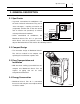
Operation Section 7 2. GENERAL DESCRIPTION 2.1 Spot Cooler • In general, conventional air conditioners cool the entire enclosed environment. They act as “heat exchangers”, requiring an interior unit (evaporator) to blow cool air into the interior and an exterior unit (condenser) to exhaust Condenser (Outdoor Unit) Evaporator (Indoor Unit) exchanged heat to the outdoors.
Operation Section 8 3. CONSTRUCTION 3.1 Exterior Dimensions (D IA .5 .9 ) (10.6) (10.2) (1 7. (1.4) (1.4) (3.5) (3.5) (19.5) (3.6) (21.5) (3.7) (47.1) (3.7) (11.5) (43.4) (18.8) 7) (28.
Operation Section 9 3.
Operation Section 3.3 Internal Structure Fan Motor Fan (Evaporator) Evaporator Fan (Condenser) Modulating Tank High Pressure Switch Capillary Tube Condenser Drain Pan Drain Tank Compressor Drain Switch Control Box I002289 3.4 Basic Construction • The MovinCool Classic Plus 26 is compact in construction because the condenser and the evaporator are enclosed in one unit. The interior is divided into three sections.
Operation Section 11 3.5 Air Flow • Air drawn from the right side face passes through the condenser which extracts the heat. This hot air is blown out through the upper exhaust air duct. Air taken in from the front face is cooled by the evaporator and then blown through the cool air ducts. All the air inlets are equipped with filters, and the exhaust air duct is protected by metal grill. Cool Air Out Exhaust Air Out Condenser Air In Evaporator Air In I002290 3.
Operation Section 12 4. SPECIFICATIONS 4.1 Technical Specifications ITEM Electronic Features Cooling Capacity*1 Refrigerant Circuit SPECIFICATIONS Control Panel Electronic Thermostat Control Electronic Capacity-208/230 V 24000/24000 Btu/h (7034/7034 W) Compressor Compression Type Motor Rated Output at 230 V Spine Fin Condenser Spine Fin Capillary Tube Refrigerant/Enclosed quantity Ventilation Equipment For Fan Type Evaporator Max. Air Flow-high/low R-22/1.87 lb (0.
Operation Section ITEM Condensate Tank Capacity • Specifications are subject to change without notice. < NOTE > *1 : Rating Condition: 95 °F (35 °C), 60 %RH *2 : Measured at 3.28 ft (1 m) from surface of unit. SPECIFICATIONS 5 ± 0.
Operation Section 14 4.2 Characteristics (at 230 V) Cooling Capacity (x103 Btu/h) 28 23.4(13) 21.6(12) 24 19.8(11) 22 18.0(10) Delta-T °F (°C) 26 20 Dry Bulb Temp. °F (°C) 18 113(45) 104(40) 16.2(9) 14.4(8) 12.6(7) 10.8(6) 95(35) 9.0(5) 86(30) 77(25) 68(20) 7.2(4) 30 59 (15) Current Consumption (A) 3.0 2.5 80 16 14 12 2.
Operation Section 15 4.3 Characteristics (at 208 V) Cooling Capacity (x103 Btu/h) 28 23.4(13) 21.6(12) 24 19.8(11) 22 18.0(10) Delat-T °F (°C) 26 20 Dry Bulb Temp. °F (°C) 18 113(45) 104(40) 16.2(9) 14.4(8) 12.6(7) 10.8(6) 95(35) 9.0(5) 86(30) 77(25) 68(20) 7.2(4) 30 59 (15) Current Consumption (A) 3.0 2.5 80 18 16 14 2.
Operation Section 5. REFRIGERANT SYSTEM 5.1 Refrigerant System Construction The component parts of the refrigerant system include the following: • Compressor, Evaporator, Condenser, Capillary tube, High Pressure Switch, Modulating Tank These parts are all connected by copper tubing. All the connections have been brazed.
Operation Section 17 5.2 Compressor • The compressor used for the unit is hermetically sealed. The compressor and the compressor motor are in one casing. (1) Compressor theory of operation • The scroll utilizes an involuted spiral which, when matched with a mating scroll form, generates a series of crescent-shaped gas pockets between the two members.
Operation Section 5.3 Condenser • The condenser is a spine fin type heat exchange device consisting of copper tubes passing through an aluminum fin. • Heat is given off and absorbed by air being pulled across the condenser fins by the centrifugal fan and then expelled through the exhaust air duct. 5.4 Capillary Tube • The capillary tube is a long thin tube utilizing High Temp./High Pressure Liquid Refrigerant line flow resistance to serve as an expansion valve.
Operation Section 19 5.7 Modulating Tank • The modulating tank consists of a copper pipe From Evaportor and tank sections, each being separated from the other. The pipe connects to the evaporator outlet at one end and to the compressor at the other; the tank connects to the evaporator inlet. The modulating tank is covered with insulation to reduce thermal effects of ambient temperature.
Operation Section 20 6. ELECTRICAL SYSTEM 6.
Operation Section 21 6.2 Basic Operation of The Classic Plus 26 Electrical Circuit • There are two basic components used to control the operation of the Classic Plus 26 electrical system: - Control panel assembly - Control box • The control panel assembly contains the control panel, control board (with inputs for the freeze and room temperature thermistors), drain switch, high pressure switch and a microprocessor.
Operation Section 6.3 Control Box (1) Capacitors • The capacitors are used to temporarily boost the power output available to the fan motor and the compressor at start-up. • The specifications of each capacitor are listed below: Capacitor Application Voltage Rating Capacitance Fan Motor 440 VAC 12.
Operation Section 23 (2) Relay board • The relay board receives signals and outputs from the control board that contains a Dip Switch microprocessor. The relay board contains the compressor, fan on and fan mode (speed) relays. • It also contains a step-down transformer that converts the line voltage (208/230 VAC) to Temperature Scale Display Switch (°C⇔°F) Fan Mode Control Switch (STOP⇔OPERATE) 12 V. I002196 • This 12 V is then converted from AC to DC and used for relay coil activation.
Operation Section 6.4 Fan Motor • The fan motor is a single phase, induction type two-speed motor. The motor rotates the fan on both the evaporator side and the condenser side at the same time. Specifications: - Rated Voltage: 230 V, 60 Hz - Rated Output: High-550 W, Low-380 W Ground (Green/Yellow) CF1 (White) CF2 (Brown/White) J5 Low (Red) J6 High (Black) I002198 < NOTE > An internal overload relay is used to protect the fan motor.
Operation Section 25 6.6 Power Cord with LCDI • Classic Plus 26 is equipped with a UL approved LCDI cord and an approved NEMA plug configuration (6-20). The appropriate outlet must be used for this plug type. LCDI is used for monitoring leakage current. Once leakage current is detected, LCDI de-energizes the unit.
Operation Section 6.7 Drain Switch • The Classic Plus 26 is equipped with a drain tank switch. When the drain tank accumulates approximately 4.0 gal (15 L) of condensate (water) in the drain tank, the drain tank switch sends a signal to the microprocessor. The microprocessor stops all operation of the unit, flashes the "TANK FULL” LED, indicates "TANK FL” on the LCD and closes the contact of output signal. • This system utilizes a 0.1 A, 125/250 VAC micro-switch for this function.
Operation Section 27 (1) How to re-start the unit • If the LCD indicates “PROGRAM ON”, press the COOL ON/OFF button to continue running the program. If the LCD indicates “PROGRAM ON” continuously (program activated), no further steps are necessary. If no program exists or the program was deactivated, press the FAN MODE button or the COOL ON/OFF button. The unit returns to the previous temperature set point. 6.
Operation Section 6.12 Fan Mode Control Switch • The fan motor operation is controlled by relays on the relay board through a microprocessor in the control panel assembly. The fan program in the microprocessor can be changed by a DIP switch on the left side of the relay board located in the control box.
Repair Section 29 7. TROUBLESHOOTING 7.1 Troubleshooting • Before troubleshooting the system, the following inspection should be performed. (1) Inspection of power source voltage • Check the voltage of the power source. - Single phase 208/230 V (60 Hz) • Check the operation and condition of the fuse or circuit breaker in the power source. (2) Inspection of air filters • Remove the air filters and check the element.
Repair Section 30 7.2 Self-Diagnostic Codes • Self-diagnostic codes are displayed on the control board under the following conditions and clear method is as follows. LCD Display Description Drain tank is full Condition When the drain tank is filled with drain water. (“TANK FL” LED flashes and signal Reset/Remedy 1) Drain away. (LCD indicates “TANK”) 2) Press ON/OFF button. output (J106) turns on.) TU AM HI Condensate pump When (optional) condensate pump 1) Fix the condensate pump.
Repair Section LCD Display Description MO TU WE TH FR SA SU AM START CLOCK Press HI/LO and U buttons After 5 sec., display goes back to all on mode simultaneously for 3 sec. normal mode. (To check LCD segments and LED PM LOCKED F C HI FAN LO ON COOL OFF Reset/Remedy Show LCD and LED PROGRAM ON STOP Condition F C display.) SET TEMP ROOM TEMP TU AM Key lock mode (LCD Press ENTER and SET CLOCK Press ENTER and SET CLOCK displays “LOCKED”.) buttons simultaneously for 5 sec.
Repair Section 32 LCD Display Description TU Condition Reset/Remedy Activation of high When high pressure switch Find the cause of high pressure to pressure switch (connected to J104) activates address it. (=J104 input turns to open) 3 times Check the following. in 24 h, “HP” is indicated and signal Ambient air temperature output (J106) turns on.
Repair Section 33 Possible Cause Symptom Remedy Checking Area 1. Usage conditions Cause Operation near usage limits. (high temperature). 2. Dirt in condenser or Compressor operates. Air volume normal Review the installation place. Insufficient heat exchange. Clean fins. evaporator. 3. Frost in refrigeration cycle. Clogging at the frost section. Replace clogged section. 4. No temperature difference Insufficient refrigerant.
Repair Section 34 (2) Unit does not start (operate) < NOTE > • In this case, there is a possibility of safety device activating due to the clogged air filter. So make sure to first clean the air filter and then start up again to confirm if the problem lies with the air filter. • Check the installation site for operating temperature and installation space (unobstructed airflow). Possible Cause Symptom Remedy Checking Area Does not operate at all 1. Voltage. Power failure. Repair power. 2.
Repair Section 35 Possible Cause Symptom Remedy Checking Area 1. Display code “FL”. Cause Drain tank (optional) is filled Discharge the drain water. with the drain water. Improper drain switch Check connection. connection. 2. Display code “AS”. Defective drain switch. Replace drain switch. Improper routing of drain Repair drain hose, then reset hose. unit. To RESET: Press ON/OFF and HI/LO buttons on the control box simultaneously for 5 sec. Defective condensate pump.
Repair Section 36 Possible Cause Symptom Remedy Checking Area Cause 1. Fan on-off relay on the relay board. Control immediately panel after display starting normally. Replace relay board. contact. 2. Fan HI/LO change relay on Stops Open circuit or insufficient the relay board. Open circuit or insufficient Replace relay board. contact. 3. Fan motor insulation Insulation failure on fan resistance. Replace fan motor. motor. 4. Compressor relay on the relay board.
Repair Section 37 (4) Abnormal noise or vibration • To prevent abnormal noise or vibration, carefully determine the source of the problem and come up with proper countermeasures to solve the problem so that it does not occur again. Possible Cause Symptom Remedy Checking Area 1. Fan. Abnormal noise or vibration. Cause Fan interference. Repair interfering section. Fan deformation. Replace fan. 2. Compressor fixing nuts. Looseness of nuts. Tighten nuts further. 3. Piping. Pipe interference.
Repair Section (3) Inspection of cooling capacity performance • Measure the difference in temperature between the inlet of the evaporator and the cool air vent. If the difference is out of the range given in the graphs on page 14 and 15, proceed with the remedy suggested in the troubleshooting chart on page 32 to 37.
Repair Section 39 8. DISASSEMBLY 8.
Repair Section 40 8.2 Disassembly 1) Remove drain tank. I002299 2) Remove eight (8) screws from ducts. Then Screws (4) remove two (2) ducts. Screws (4) I002300 3) Remove four (4) screws from service panel. Screws (4) I002301 4) Remove thirteen (13) screws from rear panel.
Repair Section 41 5) Remove twelve (12) screws from upper panel Screws (2) and two (2) screws from blower housing (condenser). Screws (2) Screws (4) Screws (4) (Back side) Screws (2) I002303 6) Remove eight (8) screws from left panel. Screws (4) Screws (4) I002304 7) Remove seven (7) screws from right panel.
Repair Section 8.3 Removal of Electrical Parts (1) Control box 1) Remove four (4) screws from service panel. (See page 40.) 2) Remove electrical parts. - Terminal block: Remove two (2) screws from control box. - Capacitor: Remove two (2) screws from control box.
Repair Section 43 (2) Relay board 1) Remove four (4) screws from service panel. (See page 40.) 2) Disconnect seven (7) connectors, and remove five (5) screws from relay board.
Repair Section 2) Disconnect the following connectors from the B C D E A control board: (A) J201 (10-pin) Wire Harness, Relay Board to Control (B) J101 (2-pin) Room Temperature Thermistor (C) J102 (2-pin with black tape) Freeze Protection Thermistor F G I002307 (D) J103 (2-pin) Drain Tank Switch (E) J104 (2-pin) High Pressure Switch (F) J106 (2-pin) Not in use. (G) J108 (2-pin) Not in use.
Repair Section 45 (4) Battery replacement of control board • When the power is unplugged from the unit, and control board is automatically resetting clock and program, it is time to change the battery on the control board to avoid resetting of clock and program. 1) Disassemble control board. (See page 43 and 44.) Control Board Battery I001805 2) See diagram for battery removal.
Repair Section 8.
Repair Section 47 (1) Removal of condenser fan 1) Loosen the set screw using a hex key. Then remove condenser fan. Set Screw I002217 (2) Removal of evaporator fan and fan motor 1) Remove two (2) nuts on the inside of the condenser fan casing in the locations shown. Then remove condenser fan casing. Nut (1) Nut (1) I002218 2) Remove two (2) nuts and two (2) screws as Nut (1) Nut (1) shown. Then remove the motor stay together with the fan motor.
Repair Section 8.5 Inspection of Capacitor (for Fan Motor and Compressor) (1) Ohmmeter method • Set the ohm-meter to the 10M range. Place the two probes against the two terminals of the capacitor. At first, the ohm-meter should indicate small value, then the reading should gradually increase towards infinity. This indicates that the capacitor is charging. If the reading indicates infinity right away (open) or the ohm-meter fails to move from 0. (shorted), I001808 replace the capacitor.
Repair Section 49 8.7 Inspection of Fan Motor • Measure resistance across the terminals of the fan motor. (All terminals must be disconnected from the unit.) • Between terminals (at 77 °F (25 °C)) - J6-CF1 Approx. 6.8 ohm - J6-CF2 Approx. 10.5 ohm - CF1-CF2 Approx. 19.0 ohm • If the measured resistance is not equal to these Ground (Green/Yellow) CF1 (White) CF2 (Brown/White) J5 Low (Red) J6 High (Black) I002198 standard values, replace the fan motor. 8.
Repair Section 8.11 Inspection • In most cases, the probable cause for insufficient cooling is a clogged system, leakage or an incorrect amount of refrigerant. In such cases, inspect the system according to the following procedure. (1) Inspection of clogged system • Check the component parts of the refrigerant system, including piping, that could be clogged with refrigerant. If clogged with refrigerant, only the clogged part is frosted partially. In such a case, change the part in question.
Repair Section 51 9. REFRIGERANT SYSTEM REPAIR 9.1 Repair of Refrigerant System • In case there is a leak, obstruction, or trouble in the refrigerant system of the Classic Plus 26, replace or repair the part in question. After replacing any component all connections must be brazed. (1) Proper brazing techniques • It is desirable to use a slightly reducing flame. Oxyacetylene is commonly used since it is easy to judge and adjust the condition of the flame.
Repair Section (4) Use of dry nitrogen gas • During brazing, the inside of the pipe undergoes an oxidative reaction due to the brazing flame. Introduce dry nitrogen gas (0.27 gal/min (1 L/min); adjust with the flow regulator) through the pinch-off tube of the refrigerant. < NOTE > Take care not to allow dirt, water, oil, etc. to enter into the pipe. (5) Vertical Joint • Heat the whole brazed fitting to a proper brazing temperature.
Repair Section 53 9.2 Removal of Refrigeration Cycle Components CAUTION • Before any refrigeration cycle component can be replaced, it is necessary to recover the refrigerant using standard recovery procedures and equipment. • To prevent oxidation, dry nitrogen should be conducted (flow rate 0.27 gal/min (1 L/min)) through the pinch-off tube during any brazing operation. • During any component replacement involving brazing, shield nearby parts with a steel plate, etc., to protect them from the flame.
Repair Section 54 9.3 Charging the System with R-22 Refrigerant • Always ensure that the refrigerant system has been properly evacuated before charging with the specified amount of R-22. • Equipments is only for R-22. WARNING • When handling refrigerant (R-22), the following precautions should always be observed: - Always wear proper eye protection while handling refrigerant. - Maintain the temperature of the refrigerant container below 104 °F (40 °C). - Perform repairs in a properly ventilated area.
Repair Section 55 (1) Connection of gauge manifold 1) Properly remove the crushed end of the pinch-off Charging Hose Side Refrigerant Cycle Side tube at the high pressure side and the low pressure side of the refrigerant cycle with a pipe cutter. 2) Fit the process tube fitting to the pinch-off tube on both sides.
Repair Section 56 (3) Checking vacuum Valve Setting LO HI Closed Closed Pressure Gauge 1) Leave the high pressure valve and the low Leave valves closed for 5 min or more. Pointer of pressure gauge returning to zero indicates there is a leak. pressure valve of the gauge manifold closed for five min or more, and confirm that the gauge pointer does not return to zero.
Repair Section 57 (4) Checking gas leak 1) Remove the charging hose (green) from the Valve Setting vacuum pump, and connect the hose to the LO HI Closed Closed Air Purging refrigerant cylinder (R-22). Charging Hose Red (Green) To Process Tube Fitting 2) Loosen the nut on the gauge manifold side of the Refrigerant Cylinder R-22 Open The Valve of Refrigerant Cylinder charging hose (green). 3) Open the valve of refrigerant cylinder perform air purging in the charging hose (green).
Repair Section (5) Evacuation (repeat) 1) Close the valve of the refrigerant cylinder. Then Valve Setting Gauge LO HI Closed Open LO HI Closed Closed 30 inHg (100 kPa) or larger Low Pressure Valve High Pressure Gauge High Pressure Valve remove the charging hose (green) from the refrigerant cylinder, and connect it to the refrigerant recovery machine. < NOTE > High Pressure Side Tube Vacuum Pump (in Operation) Keep the high pressure valve and the low pressure valve of the gauge manifold closed.
Repair Section 59 9.4 Refrigerant Charging Work (1) Refrigerant charging 1) Remove the charging hose (green) from the Valve Setting vacuum pump, and connect it to the refrigerant LO HI Closed Closed Air Purging cylinder (R-22). Charging Hose Red (Green) To Process Tube Fitting 2) Loosen the nut on the gauge manifold side of the Refrigerant Cylinder R-22 Open The Valve of Refrigerant Cylinder charging hose (green). Open the valve of the charging hose (green).
Repair Section (2) Removal of gauge manifold 1) Crimp the pinch-off tube with a pinch-off tool. Pinch-Off Tool Pinch-Off Tube 2) Remove the gauge manifold and the process To Gauge Manifold Side tube fitting. Crush the end of the pinch-off tube. 3) Braze the end of the pinch-off tube. Charging Hose To Refrigerant Cycle Side 4) Ensure that a gas leak is not present at the pinched off portion and the brazed end.
Repair Section 61 10. REASSEMBLY 10.1 Removal of Unit • Reassemble the unit in the reverse order of removal. Described below are the parts that require special care in reassembling the unit. Perform all wiring or rewiring as referenced in the wiring diagram. 10.2 Compressor Mounting • Mount the compressor on the frame, using cushions, steel collars, spring washers, plate Nut washers and nuts. Spring Washer Plate Washer Cushion Steel Collar I001818 10.
Repair Section 10.5 Perform the Inspection • Perform the inspection of cooling performance and check for abnormal noise or abnormal vibration. 10.6 Caster Maintenance • Lubricate bearings in caster as needed with standard bearing grease using the zerk fitting. < NOTE > Casters should roll and swivel freely. Check for dirt or dust build up. Remove dust or dirt build up.
Repair Section 63 10.
DENSO SALES CALIFORNIA, INC. Long Beach, CA 90810 www.movincool.