
Service manual


Operation Section
20
6. ELECTRICAL SYSTEM
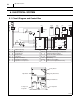
6.1 Circuit Diagram and Control Box
I002295
AC 208/230 V 1φ 60 Hz
AP
G
G
G
HI
LO
MC
CN RTH THSDS
CB
HPRS
J106
J108
J105
J101 J102 J103 J104
J201
3
2
1
Jumper
Line
IOLC
MF
IOLF
12
CF
CC
12
G
G
T R
J9
J8
RB
J6
J5
J4
J3
J2
J1
AP
TB
C B
R B
MF
M C
C F
CC
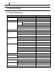
Attachment Plug
Terminal Block
Control Board
Relay Board
Fan Motor
Compressor Motor
Capacitor for Fan Motor
Capacitor for Compressor
I O LF
I O L C
DS
THS
R TH
G
HPRS
C N
Inner Overload Relay of Fan Motor
Inner Overload Rela
y of Compressor
Full Drain Warning Switch
Freeze Protection Thermistor
Room Thermistor
Grounding
High Pressure Switch
Connector for Option Drain Pump
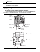
TB
Relay Board Fuse
Relay Board
Terminal Block
Fan Capacitor
Dip Switch
Compressor
Capacitor