OPERATION MANUAL OFFICE PRO W20 Unit Serial Number Range: 0211XXXXW20 to Present (From February 2011 to Present) READ THIS MANUAL CAREFULLY FOR INSTRUCTIONS ON CORRECT INSTALLATION AND USAGE, AND READ ALL SAFEGUARDS SECCIÓN EN ESPAÑOL SECTION EN FRANÇAIS AVAILABLE AT WWW.MOVINCOOL.
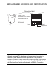
SERIAL NUMBER LOCATION AND IDENTIFICATION Nameplate Label COOLING AMPS. WITH PUMP COMPR. OUTPUT REFRIGERANT/TOTAL CHARGE DESIGN PRESSURE LO/HI PART NO./WEIGHT SERIAL NO. Nameplate Label Position Month Year Model Sequential Number © 2015 DENSO PRODUCTS AND SERVICES AMERICAS, INC. All rights reserved. This book may not be reproduced or copied, in whole or in part, without the written permission of the publisher. DENSO PRODUCTS AND SERVICES AMERICAS, INC.
OPERATION MANUAL OFFICE PRO W20
Table of Contents SERIAL NUMBER LOCATION AND IDENTIFICATION ................................... 2 FOREWORD ...................................................................................................... 5 Definition of Terms................................................................................ 5 GENERAL WARNINGS & CAUTIONS.............................................................. 6 INVENTORY.................................................................................................
FOREWORD Congratulations on purchasing the MovinCool portable air conditioner. This manual explains how to install and operate the MovinCool Office Pro W20 portable air conditioning unit. Please read this operation manual thoroughly to familiarize yourself with the features of the unit and to ensure years of reliable operation. You may also find it useful to keep this operation manual on hand for reference. Components and/or procedures are subject to change without prior notice.
GENERAL WARNINGS & CAUTIONS 1. All electrical work should only be performed by qualified electrical personnel. Repair to electrical components by non-certified technicians may result in personal injury and/or damage to the unit. All electrical components replaced must be genuine MovinCool parts, purchased from an authorized reseller. 2. The power supply for this unit should be a dedicated single outlet circuit with UL recognized short-circuit and ground-fault protective breaker. 3.
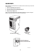
INVENTORY After unpacking your MovinCool unit, please check to make sure you have the following items: 1. Office Pro W20 MovinCool Unit (1) 2. Operation Manual/Product Registration (1) 3. Garden Hose Adapter (2) Note: If any of these items were not included in the box or appear damaged, please contact your MovinCool reseller for replacement.
INSTALLATION Choosing an Installation Site CAUTION: Following are some precautions to consider before choosing your installation site. Please review carefully as improper installation may result in personal injury or damage to the unit. 1. Do not use the unit in areas where leakage of flammable gas may occur. 2. Do not use the unit in areas where it is exposed to rain or water. 3. Do not use the unit in an environment which contains excessive amounts of corrosive gas or vapor. 4.
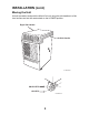
INSTALLATION (cont.) Moving the Unit Unlock the casters and push the MovinCool unit using the side handles to a flat, level surface and set the casters back to the LOCKED position.
INSTALLATION (cont.) Water Pipe or Hose Connection WARNING: Before plugging in the unit, connect the water line to the unit. To avoid electrical shock, make sure that there is no water splashed onto the electrical box or the power cord. Office Pro W20 unit has two female 1/2 inch NPT (National Pipe Thread) water connections.
INSTALLATION (cont.) Water Pipe or Hose Connection (cont.) Connecting Water Pipes (cont.) 4. Make sure that water pipes are connected properly to the unit, and there is no water leakage. CAUTION: Supply water pressure limitation of the unit is maximum 150 psi (1,034 kPa). Do not use the unit with water which contains a high corrosive factor. Note: 1.
INSTALLATION (cont.) Water Pipe or Hose Connection (cont.) Connecting Optional Water Hoses (cont.) 4. Connect the optional water hoses to the garden hose adapters. Hold the hoseend connector with the wrench B tightly to prevent hose rotation. Then tighten the swivel nut with the wrench A. CAUTION: Use two proper size wrenches. WRENCH B WRENCH A ILL00208-00 5. Connect the other end of the garden hoses to the water source. 6.
INSTALLATION (cont.) Plugging in the Unit 1. Check the prongs and surface of the power cord plug for dust/dirt. If dust and/ or dirt are present, wipe off with a clean, dry cloth. 2. Check the power cord, plug and prongs for damage or excess play. If any damage or excess play is found, contact your MovinCool reseller or a qualified technician for repair. WARNING: 1. If the power cord or plug is damaged, replacement should only be performed by qualified electrical personnel. 2.
INSTALLATION (cont.) Warning Signal Connection (Output Signal Terminal L+ and L-) The controller is equipped with a warning signal output relay type (Form C, normal open dry contact) which can be used to monitor the failure conditions. Relay contactor is closed when any of the following conditions has occurred: a. Tank full b. Temperature sensor fails c.
INSTALLATION (cont.) Fire Alarm Control Panel Connection (Input Signal Terminal E+ and E-) The controller is equipped with a normal open input signal connection, which can be connected directly from the fire alarm control panel. This input signal terminal should only be connected to a close or open dry contact signal. When receiving the signal from the fire alarm control panel, the unit turns off and does not turn back on until it has been RESET. Connecting Fire Alarm Control Panel to Controller 1.
INSTALLATION (cont.) LCDI Power Cord Instruction WARNING: The LCDI device is a non-serviceable device. Attempting to open the device may expose the user to the hazards of electric shock, and could void warranties of this product. Manufacturer's reliability is limited to the replacement of the device. CAUTION: 1. Read the attention printed on the device for proper use and handling of this device. 2. This device is used for monitoring leakage current. 3. Do not immerse in water. 4.
FEATURES 1. A digital electronic control panel, which allows the user to easily control the unit’s operation. 2. Dual fan speeds (either HIGH or LOW) in both COOL and FAN ONLY modes. 3. Digital LCD display with blue backlight that indicates: a. Clock with day and time b. Room temperature and set point temperature (either Fahrenheit or Celsius) c. Fan speed status d. Cool mode status e. Program start time and stop time f. Program run and stop g. Status codes h. Keypad lock 4.
OPERATION Control Panel Before operating the unit, it is important to familiarize yourself with the basic controls located on the control panel. 7 6 8 2 5 1 4 3 ILL00052-00 1. COOL Mode Button 2. FAN Mode Button 3. SET TEMP Buttons ( 4. 5. 6. 7. 8. ENTER Button SET CLOCK Button SET PROG Button RUN/STOP Button TANK FULL LED / Activates/deactivates the COOL mode and turns the unit off. Activates/deactivates the high, low, and off fan speed.
OPERATION (cont.) Control Panel (cont.) LCD Indicators 9 14 11 15 12 13 16 19 10 17 18 ILL00053-00 9. MO...SU 10. °C or °F 11. 12. 13. 14. 15. 16. 17. 18. 19. AM/PM PROGRAM PROGRAM ON START STOP CLOCK FAN HI/LO COOL ON/OFF LOCKED Illuminates to indicate selected day of the week. Temperature displayed in either Fahrenheit or Celsius (see Note). Illuminates to indicate AM or PM time of day. Blinking during program editing mode. Illuminates to indicate program is running.
OPERATION (cont.) Operating Modes The Office Pro W20 can be operated in two modes, FAN ONLY and COOL. When in FAN ONLY mode, the unit circulates the surrounding air. When in COOL mode, the compressor is operated and cool air is circulated. 1. COOL Mode Once the compressor has been disengaged for more than 120 seconds, the unit operates in FAN ONLY mode for approximately 5 seconds before the compressor re-engages. 2.
OPERATION (cont.) Set Clock Prior to operating the Office Pro W20 users should set the clock of the controller to the correct time as shown in the following steps: 1. Press and hold the SET CLOCK button for 3 seconds or until beep. (LCD indicates blinking “CLOCK” and blinking “day of the week”.) 2. Press SET TEMP buttons to scroll day of the week. 3. Press ENTER button. Step 1 & 6 4. Press SET TEMP buttons to select correct hour. Step 2 to 5 5. Press ENTER button. 6.
OPERATION (cont.) Operating in FAN ONLY Mode 1. The unit can also be operated in FAN ONLY mode by pressing FAN HI/LO button (LCD indicates “FAN HI/LO” and “COOL OFF”). 2. The unit can then be turned off by pressing the FAN HI/LO button until fan turns off (FAN ONLY mode speed sequences are HI→LO→OFF). Changing from FAN ONLY Mode to COOL Mode The COOL mode can be activated while the unit is operating in FAN ONLY mode. To do this, simply press the COOL ON/OFF button (LCD indicates “COOL ON”).
OPERATION (cont.) How to Set a Program SET START TIME 1. Press and hold the SET PROG button for 3 seconds or until beep. 2. Press SET TEMP buttons to scroll day of the week. 3. Press ENTER button. Step 1 & 18 4. Press SET TEMP buttons to select desired hour. 5. Press ENTER button. Step 2 to 17 6. Press SET TEMP buttons to select desired minute. 7. Press ENTER button. ILL00055-00 SET STOP TIME 8. Press SET TEMP buttons to scroll day of the week. 9. Press ENTER button. 10.
OPERATION (cont.) How to View and Delete Program 1. Press and hold the SET PROG button for 3 seconds or until beep. 2. To view edited program - While pressing and holding the SET PROG button, press SET TEMP buttons ( / ) to scroll program sequence. 3. To delete a program - Press ENTER and SET PROG buttons once simultaneously. 4. To delete multiple program - Press and hold ENTER and SET PROG buttons simultaneously. How to Run and Stop Program 1.
OPERATION (cont.) Self-Diagnostic Codes Self-diagnostic codes are displayed on the control board under the following conditions. LCD Display Codes Condition When the drain tank switch shuts off the unit, LCD displays “TANK FL” and “TANK FULL” LED flashes. Once emptying the drain tank procedure is completed and ON/OFF has been pushed, unit returns to normal operation.
OPERATION (cont.) Empty the Drain Tank During COOL mode, condensate water accumulates in the drain tank. When the drain tank becomes full, the “TANK FULL” LED flashes and the LCD displays “TANK FL” and the unit turns off automatically. Note: If you want to empty the drain tank, while the unit is in operation, press the COOL ON/OFF button to turn the unit off. If a program is running, you must first stop the program by pressing the RUN/STOP button. 1. Open the drain tank door. 2.
OPERATION (cont.) Condensate Pump Kit (Optional) A condensate pump kits are available to allow continuous operation and to eliminate the need for a drain tank. When the water collects to level (A) in the pump reservoir, the condensate pump begins to operate and discharge the water. ILL00064-00 Note: The compressor does not operate while the condensate pump is discharging the water. When the water level drops below level (B), the condensate pump stops, and the compressor restarts.
INSPECTION & MAINTENANCE Empty the Drain Tank To empty the drain tank, refer to instructions on page 26. Clean the Air Filter Clean the air filter once a week. If the unit is used in a dusty environment, more frequent cleaning may be required. A dirty air filter can reduce air output resulting in a decrease in the cooling capacity. Filter Removal Method 1. Turn the unit off by pressing the COOL ON/OFF button. If a program is running, you must first press the PROGRAM RUN button. 2. Remove the air filter.
INSPECTION & MAINTENANCE (cont.) Water Regulating Valve This unit is equipped with a water regulating valve to operate within wide water temperature range. This water regulating valve automatically controls the water flow rate to stabilize the refrigeration system and it has an adjusting bolt to adjust the valve opening temperature.
INSPECTION & MAINTENANCE (cont.) Water Regulating Valve (cont.) Adjustment of Water Regulating Valve Setting 1. Stop the unit and unplug the power cord. Then shut off the water supply. 2. Remove five (5) screws from the service panel on the rear side of the unit. SCREWS (5) ILL00156-00 3. Remove thirteen (13) screws from the rear panel. SCREWS (3) SCREWS (7) SCREWS (3) ILL00168-00 4. Check the valve setting guide table on the inside panel of the unit to confirm the current valve setting.
INSPECTION & MAINTENANCE (cont.) Water Regulating Valve (cont.) Adjustment of Water Regulating Valve Setting (cont.) 6. Rotate the adjusting bolt with a wrench to adjust the valve temperature setting according to the “Valve Setting Guide Table” on page 32. The painted line on adjusting bolt and housing is for rotational reference to complete one rotation (360°).
INSPECTION & MAINTENANCE (cont.) Water Regulating Valve (cont.) Adjustment of Water Regulating Valve Setting (cont.) 7. Write the value setting with a permanent marker on the adjustment record table on the inside panel of the unit. Note: Recording the value setting is very important for reference when making future adjustments. Valve Setting Guide Table SETTING DIRECTION OF VALVE ROTATION A Clockwise NUMBER OF VALVE OPENING MINIMUM WATER ROTATION TEMPERATURE TEMPERATURE 4 72 °F (22 °C) 40 °F (4.
INSPECTION & MAINTENANCE (cont.) In-Season/Off-Season Inspection & Maintenance In-Season WARNING: To prevent an accident due to electrical shock, perform inspection and maintenance only after unplugging the power cord. 1. Check the prongs and surface of the power cord plug for dust and/or dirt. If dust and/or dirt are present, wipe off with a clean dry cloth. 2. Check the power cord, plug and prongs for damage or excess play.
TROUBLESHOOTING Check the following conditions before calling your MovinCool reseller or a qualified technician. CONDITION POSSIBLE CAUSE REMEDY Unit does not operate. 1. Ground fault breaker trip or LCDI power cord trip. Reset breaker or reset power cord. 2. Drain tank is full. Empty the drain tank. (“TANK FULL” LED flashes.) Insufficient cooling. 3. High pressure switch activated 10 times in 24 hours. 1. Check environmental condition whether it is within operation range or not (see page 36). 2.
TECHNICAL SPECIFICATIONS ITEM SPECIFICATIONS Electronic Features Operation Digital Programmable Electrical Characteristics Voltage Requirement Single-Phase, 115 V, 60 Hz Operating Voltage Max. Range Min. 127 V 104 V Recommended Fuse Size 15 A Cooling Capacity and Power Consumption Air: 80 °F (27 °C), 50 %RH Total Cooling Capacity Water (EWT/LWT): 85 °F /95 Sensible Cooling Capacity °F (29 °C/35 °C) Power Consumption Current Consumption 15,700 Btu/h (4,590 W) 10,800 Btu/h (3,180 W) 1.28 kW 11.
TECHNICAL SPECIFICATIONS (cont.) ITEM Operating Condition Range SPECIFICATIONS Inlet Air Temperature Max. 95 °F (35 °C), 60 %RH Min. 65 °F (18 °C), 50 %RH Entering Water Temperature*1 Max. 90 °F (32 °C) Min. 40 °F (4.4 °C) Water Pressure Recommended Water Flow Rate 150 psi (1,034 kPa) or less 5 gal/min (18 L/min) Maximum Duct Length Cold Duct 25 ft (7.6 m) Sound Level*2 High 62 dB (A) Low 60 dB (A) • Specifications are subject to change without notice.
WARRANTY STATEMENT DENSO PRODUCTS AND SERVICES AMERICAS, INC. ("DENSO") warrants its MOVINCOOL Products only to the extent stated in its official written warranties.
P/N: GX484007-3313EN Fourth Issue: April 2015