Smartio C104 PCI Series Smart 4 Port Serial Board for PCI bus Nov.
Copyright Notice Copyright 1998, 1999 Moxa Technologies Co., Ltd. All rights reserved. Reproduction without permission prohibited. MOXA is a registered trademark of Moxa Technologies Co., Ltd. All other trademarks or registered marks in this manual belong to their respective manufacturers. Disclaimer Information in this document is subject to change without notice and does not represent a commitment on the part of Moxa.
Moxa Internet Services Customer’s satisfaction is always our number one concern. To ensure that customers get the full benefit of our services, Moxa Internet Services have been built for technical support, product inquiry, new driver update, user’s manual update, etc. The followings are the services we provide. E-mail for technical support address: support@moxa.com.tw FTP site for free driver update address: ftp.moxa.com or ftp.moxa.com.
Manual Organization This manual is composed of six chapters and one appendix. This manual is written for installers, system administrators and software programmers. If you are a first-time installer and system administrator, we recommend you to go through the whole manual except chapter 4. If you are a software programmer, you may refer to chapter 4, “Serial Programming Tools”. If you need cable wiring information, please see the “Connection Cable and Cable Wiring” chapter.
Table of Contents Chapter 1 Introduction................................................................1 1.1 1.2 1.3 1.4 Overview................................................................................................... 1 Features ................................................................................................... 2 Check List................................................................................................. 3 Installation Guide........................................
.2 Windows NT ........................................................................................... 21 6.3 Windows 95/98....................................................................................... 21 Appendix Technical Reference................................................21 A Specification.............................................................................................. 21 B PCI ...............................................................................................
Chapter 1 Introduction 1.1 Overview Smartio - The Smart Multiport Async Solution The term Smartio stands for smart multiport serial I/O solution. The Smartio C104 PCI Series boards, including C104H/PCI and C104HS/PCI, are designed for 32-bit PCI bus with “Plug and Play” feature.
Chapter 1 l l Introduction Surge Protection To prevent the boards from damage caused by lightning or high potential voltage, TVSS (Transient Voltage Surge Suppressor) technologies are introduced in some connection options to protect the multiport controller. This is critical to harsh environment such as factory, severe weather such as lightning, or other high interference situations.
Introduction l l Chapter 1 C104 PCI Series 3 3 Windows NT Windows 95/98 3: Driver supported by Moxa and shipped with product Note: Download the newest drivers from the MOXA FTP service 1.3 Check List Upon unpacking the Smartio C104 PCI Series, you should find the following items in the package: v v v v Smartio C104 PCI Series 4 port serial board Device driver diskettes: l Windows NT and Windows 95/98 Version 1.1 or above¡Ñ1 l PComm Lite Version 2.
Chapter 1 l l Introduction 1.4 Installation Guide This section gives a brief summary of how to install the Smartio C104 PCI Series under each supported operating system. The installation is simple and involves the following stages: Check the PCI BIOS settings Install the Smartio C104 PCI Series board and the connection cable See chapter 2 Install the software from the diskette Configure the driver for the board and ports See respective O.S.
Chapter 2 Hardware Installation The installation of the Smartio C104 PCI Series consists of hardware and software installation. The respective sections of the operating systems in the next chapter deal with the software installation. The hardware installation is detailed in this chapter. The no-switch-no-jumper Smartio C104 PCI Series board’s hardware configuration for IRQ number and I/O addresses is automatically assigned by the PCI BIOS.
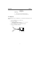
Chapter 2 l l Hardware Installation 2.2 Connecting the Fan-out Cable Step 7: Connect the connection cable. P1 P2 P3 P4 Step 8: Smartio C104 PCI Series Power on the PC and the BIOS will automatically set the IRQ and I/O address. Note ! Each board must occupy one unique IRQ and four 8-byte I/O addresses, which are assigned automatically by the PCI BIOS.
Chapter 3 Software Installation In this chapter, the software driver installation, configuration and driver update/removal procedures are described for various operating systems, including Windows NT and Windows 95/98. Before proceeding with the software installation, complete the hardware installation detailed in previous chapter. However, if it is necessary for you to develop your own applications, please refer to the next chapter, “Serial Programming Tools”, for serial programming issues. 3.
Chapter 3 l l Software Installation 1. Please log in NT as Administrator. 2. Open the [Control Panel], click on the [Network] icon and select the [Adapters] tab. 3. Click on the [Add] button, then the [Have Disk...] button in “Select Network Adapter”. 4. Specify the exact path of the driver diskette, A:\WINDOWS.NT. Then click [OK].
Software Installation l l Chapter 3 5. Select “MOXA Smartio/Industio PCI series multiport board” in the “Select OEM Option” dialog box, and click [OK] to start the installation. 6. The “MOXA Configuration Panel” dialog box appears. In the “MOXA Configuration Panel” dialog box, only the boards physically plugged and detected, whether configured or not, will be displayed. For configured boards, the COM number field is defined.
Chapter 3 l l Software Installation Click [Properties] to bring up the “Port Setting” dialog box to setup the selected board with the correct “COM Number”. è In this panel, you may: l Click [OK] to confirm the configuration changes you made. l Click [Cancel] to leave the dialog box with the configuration unchanged.
Software Installation l l Chapter 3 In the “Advanced Setting” dialog box, you may customize the driver with the following two features: l Rx FIFO trigger level Rx FIFO trigger levels, at 1, 4, 8 or 14 bytes, are available, and the default value is 14 bytes. l Tx FIFO size Tx FIFO sizes from 1 to 16 bytes are available, and the default value is 16 bytes. 7. Click [OK] on all the dialog boxes to finish the configuration and exit the “MOXA Configuration Panel” dialog box. 8.
Chapter 3 l l Software Installation 10. Once the system restarts, you may check the event log issued by the MOXA driver to see if the ports of the board are initialized successfully. l Enter the [Administrative] group, click on the [Event Viewer] icon and select [Log] and [System] to check a message similar to “MOXA C104 PCI, with serial ports COM3 to COM6, has been enabled” for each configured board.
Software Installation l l Chapter 3 2. Select “MOXA Smartio/Industio PCI Series Adapter” in “Network Adapters”. 3. Click on the [Properties] button to open the “Smartio/Industio PCI Series Boards Configuration” dialog box. Please see steps 6-10 in the previous section, “Installing Driver”, for more details. 3.1.3 Adding/Removing the Board Following is the procedure to add/remove Smartio C104 PCI Series boards after a first time installation.
Chapter 3 l l Software Installation 3.1.4 Updating the Driver To update the driver for the Smartio C104 PCI Series board, simply remove the driver, as described in the next section, and then reinstall it as detailed in the “Installing the Driver section. 3.1.5 Removing the Driver To remove the driver for the Smartio C104 PCI Series board, 1. Open the [Control Panel], click on the [Network] icon, and select the [Adapters] tab. 2.
Software Installation l l Chapter 3 3.2 Windows 95/98 Windows 95/98 supports up to 128 serial ports, from COM1 to COM128. To fully integrate the advanced features of Windows 95, multi-process and multi-thread, pure 32-bit Windows 95 virtual device port drivers (VxD) compliant with communication drivers (VCOMM) are developed for the Smartio C104 PCI Series and other MOXA multiport boards. The drivers conform to the Win32 COMM API standard.
Chapter 3 l l Software Installation The following flow chart illustrates the driver installation stages of the Smartio C104 PCI Series boards. Each stage is detailed later.
Software Installation l l Chapter 3 First Time Driver Installation Stage This stage presents the steps for installing the driver for the very first time with the first Smartio C104 PCI Series board. The installation of the Smartio C104 PCI Series board for Windows 95 and Windows 98 differs slightly and will be described in two columns. Follow the steps in the left or right column for Windows 95 or 98, respectively. 1.
Chapter 3 l l Software Installation 3. Type “A:\Windows.95” in the Location field, and click [OK]. The system will start reading the files from the diskette. 3. Select “Other Devices” and click [Next>]. 4. Clink on the [Finish] button. 4. Click on the [Have Disk] button. 5. Type “A:\Windows.95” and click [OK]. The system will start reading the files from the diskette.
Software Installation l l 6. Click [Next>]. 7. 19 Click [Next>].
Chapter 3 l l Software Installation Port Configuration Stage This stage displays the “MOXA C104 PCI Series Installation” dialog box for the port configuration. Here you can map the MOXA ports to the system COM numbers. è In the “C104 PCI Series Installation” dialog box, the COM number field of the newly installed board is undefined. You have to set up all the ports of the board with the desired “COM Number”.
Software Installation l l Chapter 3 Board and Port Ready Stage Click [OK] for all the dialog boxes to finish the configuration and exit the “MOXA Ports Installation” dialog box. In this last stage, you will complete the driver installation. Windows 95 Windows 98 After the port installation, you can immediately use the COM ports of the Smartio C104 PCI Series board without restarting Windows 95. After the port installation, click on the [Finish] button.
Chapter 3 l Note ! C C l Software Installation Once the board and the driver are installed and the driver restarts successfully, you can start to develop applications with the PComm library (See “Serial Programming Tools”) or the Microsoft Win32 API. You can also execute any ready-made applications, such as PComm utility Terminal emulator (See “Serial Programming Tools”) or HyperTerminal to transmit/receive data, as well as Remote Access Service to provide dial-up networking capabilities.
Software Installation l l Chapter 3 3.2.2 COM Port Mapping If you already have installed the driver and want to re-configure the COM number for the ports under Windows 95/98, follow this procedure. 1. Open the [Control Panel], click on the [System] icon, select the [Device Manager] tab, and then [Moxa Smartio/Industio PCI series multiport board]. Select the desired C104 PCI Series board entry, click on the [Properties] button and select the [Ports Configuration] tab. è 2.
Chapter 3 l l Software Installation 3.2.3 Updating the Driver This section explains how to update the driver. 1. In the [Control Panel], click on the [System] icon, and select the [Device Manager] tab. Select “Moxa Smartio/Industio PCI series multiport board”. 2. Select the “C104 PCI Series” option. Click on the [Properties] button and then select the [Device Driver] tab. 3. Click on the [Update Driver...] button. Click then on the [Have Disk...
Software Installation l l Chapter 3 3.2.4 Removing the PCI Board This section explains how to remove the Smartio C104 PCI Series board. To remove the Smartio C104 PCI Series board, 1. Open the [Control Panel] and click on the [System] icon. Select the [Device Manager] tab and [Moxa Smartio/Industio PCI series multiport board]. 2. Select the desired Smartio C104 PCI Series board and click on the [Remove] button. Click [OK] when asked to confirm the removal of the board. 3.
Chapter 3 l l 26 Software Installation
Chapter 4 Serial Programming Tools Moxa supports some easy but powerful serial programming libraries and communication troubleshooting utilities under Windows NT and Windows 95/98. You will save a lot of developing time with the MOXA Serial Programming Tools. The following sections will detail the installation, the library and the utilities for various platforms.
Chapter 4 l l Serial Programming Tools the implementation of multi-process and multi-thread serial communication programs and hence greatly reduces developing time. For a complete library function description and sample programs for Visual C++, Visual Basic and Delphi, please click [Start] and select [Program Files] and [PComm Lite] and [PComm Lib Help], [PComm Porting Notes] or [PComm Programming Guide] or refer to the sample programs in the PComm directory. 4.
Serial Programming Tools l l Chapter 4 Monitor (for MOXA boards under Windows NT Only) A useful port status monitoring program that allows you to watch the selected MOXA COM ports’ data transmitting/receiving throughput and communication line status which are updated and displayed on the screen at time intervals. You can also click on one of the specific displayed port in order to visualize the current communication parameters and status of that port.
Chapter 4 l l Serial Programming Tools Terminal Emulator The Terminal Emulator features multi-windows and supports terminal types of VT100 and ANSI. You can transfer data interactively, send pattern periodically or transfer file using ASCII, XMODEM, YMODEM, ZMODEM and KERMIT protocols. Click [Start] and select [Program Files] and [PComm Lite] and [PComm Termianl].
Chapter 5 Connection Cable and Cable Wiring In serial data communications, the term DTE is for Data Terminal Equipment, like PC COM1/2, serial printers and terminals. The term DCE is for Data Communication Equipment, like modems. 5.1 RS-232 Cable Wiring The followings are pin assignments for the DB25 RS-232 connector. DTE, DB25 Male 2 3 4 5 6 7 8 20 TxD RxD RTS CTS DSR GND DCD DTR 2 3 4 5 6 7 8 DTR 20 TxD RxD RTS CTS DSR GND DCD Type 1: To connect the Smartio C104 PCI Series to a DTE device.
Chapter 5 l Connection Cable and Cable Wiring C104 PCI PC COM2 port, serial printer, terminal, or any DTE device C104 PCI DB25 Male DTE Device DB9 Male TxD RxD RTS CTS DSR DTR GND DCD Type 2: l 2 3 4 5 6 20 7 8 2 3 8 7 4 6 5 1 RxD TxD CTS RTS DTR DSR GND DCD To connect Smartio C104 PCI Series to a DCE device.
Serial Programming Tools l Type 3: l Chapter 4 To connect Smartio C104 PCI Series to a DTE with 3-pin wiring. If the [Hardware flow control] feature is set to “ON”, you must loop back (or short) the RTS with CTS and the DSR with DTR, DCD on the MOXA site. If [Hardware flow control] feature is set to “OFF”, you could just leave RTS, CTS, DSR, DTR, DCD open, ignoring the connection indicated in dash-lines.
Chapter 5 l l Connection Cable and Cable Wiring 5.2 DB37 Connector The following lists the pin assignments of the Smartio C104 PCI Series DB37 connector on the bracket. With this information, you may fabricate any type of fan-out cables, such as DB37 to 4 x DB9 ro DB37 to 4 x RJ45. Pin no. 1 2 3 4 5 6 7 8 9 10 11 12 13 14 15 16 17 18 19 Signal DCD3 GND CTS3 RxD3 RI4 DTR4 DSR4 RTS4 TxD4 DCD2 GND CTS2 RxD2 RI1 DTR1 DSR1 RTS1 TxD1 Pin no.
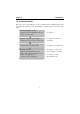
Chapter 6 Troubleshooting Common Smartio C104 PCI Series problems and possible solutions are listed below. If you still have problems, contact your dealer or Moxa for help. Or use the “Problem Report Form” at the end of this manual to report problems to your dealer at once for faster technical support. 6.1 General Troubleshooting 1. The MOXA PCI board cannot be detected by the MOXA driver while installing the driver. Hardware causes and solutions: a. The board is not installed or missing (absent).
Chapter 6 l Troubleshooting l Software Causes and Solutions: a. Smartio C104 PCI Series checks the line status (CTS) before it sends data out if the RTS/CTS flow control feature is set to “Enable” in the configuration or application program. Please refer to the “Connection Cable and Cable Wiring” chapter for proper wiring. Check the line status of the suspected port using the diagnostic LED indicators on the mini tester. b.
Troubleshooting l l Chapter 6 The possible reason is an IRQ or I/O address conflict with other ISA Bus adapters, like LAN and SCSI boards, or the system BIOS. Please refer to the corresponding problem in the previous section, “General Troubleshooting”, for solutions. 6.3 Windows 95/98 This section is specific for troubleshooting under Windows 95/98. For general problems and solutions, please see the previous section, “General Troubleshooting”. 1.
Chapter 6 l Troubleshooting l 38
Appendix Technical Reference A Specification v v Bus interface Number of ports I/O address IRQ Data bits Stop bits Parity UART Speed (bps) Connectors Data signals Surge protection Operating temp Power requirement v Dimensions v v v v v v v v v v v v : : : : : : : : : : : : : : 32-bit PCI 4 Assigned by PCI BIOS Assigned by PCI BIOS 5, 6, 7, 8 1, 1.5, 2 None, even, odd, space, mark 4¡ÑTI550C 50 ~ 921.6K 4¡ÑDB25 male RS-232¡ÐTxD, RxD, RTS, CTS, DTR, DSR, DCD, GND Max.
Appendix l l Technical Reference Due to the slot-dependency, it is necessary to re-configure the software driver once the board is plugged in different PCI slots. Up to 4 Smartio C104 PCI Series boards are allowed in a system. When installing multiple boards, please note the boards’ order for distinguishing the installed boards. C UART TI550C The UART chip, TI550C, is an intelligent asynchronous controller capable of supporting one full duplex channel that simultaneously transfers data at 921.6 Kbps.
Problem Report Form Smartio C104 PCI Series Customer name: Company: Tel: Email: Fax: Date: 1. Moxa Product: C104 PCI Series Serial Number: ________________ 2. Moxa Driver Version: ________________ 3. Moxa Hardware Settings: PCI slot number ________________________ o Windows 98 4. Operating System: o Windows 95 o Windows NT 3.51 o Windows NT 4.0 o Others 5. PC Host: Make _________ Model _________ 6. CPU: Speed _____MHz Make ______ Model ______ Make __________________ Version _______ 7. BIOS: 8.
Return Procedure For product repair, exchange or refund, you must: v Provide evidence of original purchase. v Fill out the Problem Report Form (PRF) as detailed as possible for shorter product repair time. v Obtain a Return Merchandise Authorization (RMA) number from the sales representative or dealer. v Carefully pack the product in an anti-static package, and send it, pre-paid, to the dealer.