PCI Express Board User’s Manual Multiport Serial Board for PCI Express Bus First Edition, April 2006 www.moxa.com/product MOXA Technologies Co., Ltd. Tel: +886-2-8919-1230 Fax: +886-2-8919-1231 Web: www.moxa.com MOXA Technical Support support@moxa.com.tw Worldwide: support@moxa.
PCI Express Board User’s Manual The software described in this manual is furnished under a license agreement and may be used only in accordance with the terms of that agreement. Copyright Notice Copyright © 2006 MOXA Technologies Co., Ltd. All rights reserved. Reproduction without permission is prohibited. Trademarks MOXA is a registered trademark of The MOXA Group. All other trademarks or registered marks in this manual belong to their respective manufacturers.
Table of Contents Chapter 1 Introduction ..................................................................................................1-1 Overview.................................................................................................................................. 1-2 Applications ............................................................................................................................. 1-3 Features..........................................................................
CP-104EL Specifications............................................................................................. A-2 PCI Express ............................................................................................................................ A-3 MOXA UART......................................................................................................................... A-3 Appendix B Service Information....................................................................................
1 Chapter 1 Introduction MOXA’s PCI Express serial boards meet the new slot standard for expansion boards, and work with any PCI Express slots. The boards have multiple RS-232/422/485 serial ports for connecting data acquisition equipment and other serial devices to a PC.
PCI Express Board User’s Manual Introduction Overview MOXA’s new PCI Express Multiport Serial Boards, named CP-118EL, CP-168EL, and CP-104EL, are designed for POS and ATM applications and for use by industrial automation system manufacturers and system integrators. The boards are compatible with all popular operating systems, and each of them supports data rates of up to 921.6 Kbps, and provides full modem control signals, ensuring compatibility with a wide range of serial peripherals.
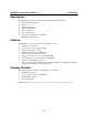
PCI Express Board User’s Manual Introduction Applications The PCI Express boards are suitable for many different applications, including: y y y y y y y y Internet/Intranet Connections Remote Access Multi-user Applications Industrial Automation Office Automation Telecommunications PC-based Vending Machines and Kiosks POS (Point-of-Sale) Systems Features The PCI Express boards have the following outstanding features: y y y y y y y y y PCI Express ×1 compliant Low profile board for compact-sized PCs Data
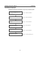
PCI Express Board User’s Manual Introduction Installation Flowchart The following flowchart provides a brief summary of the procedure you should follow to install the PCI Express boards and also provides references to chapters with more detailed information: Use the onboard DIP Switches to select the data transmission mode for each port. (CP-118EL only) Chapter 2, “Hardware Installation” Install the boards in PCI Express expansion slots.
2 Chapter 2 Hardware Installation This chapter describes the PCI Express Series hardware installation procedure. Since the BIOS automatically assigns the PCI Express board’s IRQ number and I/O addresses, you must plug in the board before installing the driver.
PCI Express Board User’s Manual Hardware Installation CP-118EL Dimensions Mode S1 S2 S3 ON OFF ON RS-422 S1 ON DIP 1 2 3 4 5 6 7 8 59.91 mm (2.36 in) S2 MU860 ON DIP 1 2 3 4 5 6 7 8 S3 ON 51.65 mm (2.03 in) RS-232 DIP 1 2 3 4 5 6 7 8 Mode S1 4-WIRE RS-485 ON S2 S3 OFF OFF 2-WIRE OFF OFF OFF RS-485 64.41 mm (2.54 in) TX1 TX2 Tx3 Tx4 Tx5 Tx6 Tx7 Tx8 RX1 RX2 Rx3 Rx4 Rx5 Rx6 Rx7 Rx8 121 mm (4.76 in) 132 mm (5.20 in) 46.9 mm (1.
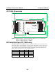
PCI Express Board User’s Manual Hardware Installation CP-168EL Dimensions 102 mm (4.02 in) MU860 54.45 mm (2.14 in) 67.21 mm (2.65 in) 121 mm (4.76 in) 62.71 mm (2.47 in) TX1 TX2 Tx3 Tx4 Tx5 Tx6 Tx7 Tx8 RX1 RX2 Rx3 Rx4 Rx5 Rx6 Rx7 Rx8 46.9 mm (1.85 in) CP-104EL Dimensions 100 mm (3.94 in) MU860 46.9 mm (1.85 in) 2-3 54.51 mm (2.15 in) 67.27 mm (2.65 in) 121 mm (4.76 in) CP-104EL 62.71 mm (2.
PCI Express Board User’s Manual Hardware Installation Plugging the Board into an Expansion Slot Since the BIOS automatically assigns the PCI Express board’s IRQ number and I/O addresses, you must plug the board into one of the computer’s expansion slots before installing the driver. Step 1: Power off the PC. WARNING To avoid damaging your system and board, make sure you turn off your computer before installing the board. Step 2: Remove the PC’s cover. Step 3: Remove the slot cover bracket if there is one.
3 Chapter 3 Software Installation This chapter gives installation, configuration, and update/removal procedures for the driver for Windows 2000, Windows 2003/XP (32-bit/64-bit), DOS, Linux (32-bit/64-bit), and SCO. Before proceeding with the software installation, complete the hardware installation discussed in the previous chapter, “Hardware Installation.” Refer to the next chapter, “Serial Programming Tools,” for information about developing your own serial programming applications.
PCI Express Board User’s Manual Serial Programming Tools Windows Drivers MOXA provides drivers that allow you to use the following serial board products under Windows 2003/XP/2000, Windows 98/95, and Windows NT. Windows 95/98/NT do not support PCI Express drivers.
PCI Express Board User’s Manual Serial Programming Tools WARNING If you are installing a PCI Express board on an ASUS A8N Series (AMD CPU) motherboard and the installation process hangs the first time, then restart the PC to reinstall it. NOTE The following steps use CP-118EL as an example. The installation process for CP-168EL and CP-104EL are the same. Windows 2003/XP (32-bit/64-bit) In this section, we describe the installation procedure for Windows XP.
PCI Express Board User’s Manual Serial Programming Tools 2. The Welcome to the Found New Hardware Wizard window will open automatically. This window will offer to connect to the Windows update site to search for a driver. Select No, not at this time and click Next to continue. 3.
PCI Express Board User’s Manual 4. Serial Programming Tools Select Search for the best driver in these locations, select Include this location in the search, and then click Browse. If the system is a 32-bit (x86) platform, navigate to the \CP-118EL\Software\Windows XP_2003\x86 folder on the CD. If the system is a 64-bit (x64) platform, navigate to the \CP-118EL\Software\Windows XP_2003\x64 folder on the CD, and then click Next to continue. The following figure shows the path for x86.
PCI Express Board User’s Manual Serial Programming Tools 5. Wait while the installation wizard searches for the correct drivers. The next window that opens cautions you that although this software has not passed Windows Logo testing, the driver has been tested and shown that it can support the Windows OS. Click Continue Anyway to proceed. 6. Wait while the driver software is installed.
PCI Express Board User’s Manual Serial Programming Tools 7. The next window shows the model name of the board, and indicates that Windows has completed the driver installation. Click Finish to proceed with the rest of the installation procedure. 8. The Found New Hardware Wizard window will open to help you install the driver for MOXA Port 0. This window will offer to connect to the Windows update site to search for a driver. Select No, not at this time and then click Next to continue.
PCI Express Board User’s Manual 9. Serial Programming Tools Select Install from a list or specific location (Advanced), and then click Next to proceed. 10. Select Search for the best driver in these locations, select Include this location in the search, and then click Browse. If necessary, use the Browse button to navigate to the \CP-118EL\Software\Windows XP_2003\x86 folder (32 bit platform) or \CP-118EL\Software\Windows XP_2003\x64 folder (64 bit platform), and then click Next to proceed.
PCI Express Board User’s Manual Serial Programming Tools The following figure shows the path for x64. 11. Wait while the installation wizard searches. The next window that opens cautions you that although this software has not passed Windows Logo testing, the driver has been tested and shown that it can support the Windows OS. Click Continue Anyway to proceed.
PCI Express Board User’s Manual Serial Programming Tools 12. Wait while the wizard installs the software. 13. After all files have been copied to the system, the Completing the Found New Hardware Wizard window will open to indicate that it has finished installing Port 0. Click Finish to proceed with the rest of the installation.
PCI Express Board User’s Manual Serial Programming Tools 14. Repeat Step 7 through Step 11 for each of the remaining seven ports. The last port to be installed will be MOXA Port 7, as shown in the following figure. 15. The Found New Hardware balloon will reappear to inform you that the hardware was installed successfully.
PCI Express Board User’s Manual Serial Programming Tools Configuring the Ports After the driver has been installed, use Device Manager to configure the CP-118EL serial ports. 1. Click Start Æ Settings Æ Control Panel Æ System, select the Hardware tab, and then click Device Manager.
PCI Express Board User’s Manual Serial Programming Tools 2. Expand the Multi-port serial adapters tab, right click MOXA CP-118EL Series (PCI Express Bus), and then click Properties to open the board’s configuration panel. 3. Click the port you would like to configure to highlight it, and then click Port Setting.
PCI Express Board User’s Manual Serial Programming Tools 4. Select a COM number for the port from the Port Number pull-down list. 5. Select the Auto Enumerating COM Number option to map subsequent ports automatically. The port numbers will be assigned in sequence. For example, if COM 3 is assigned to Port 1, then COM 4 (if not already occupied) will be assigned to Port 2, etc. 6. Select an Rx FIFO Trigger from the Rx FIFO Level pull-down list.
PCI Express Board User’s Manual Serial Programming Tools Using MOXA PComm Utility The PComm Diagnostic program is a useful tool for checking the status of MOXA’s multiport boards. The program can be used to test internal and external IRQ, TxD/RxD, UART, CTS/RTS, DTR/DSR, etc. Use this program to ensure that your MOXA boards and ports are working properly. To start the program, click Start Æ Programs Æ PComm Lite 2000(XP Ver 1.2) Æ PComm Diagnostic.
PCI Express Board User’s Manual Serial Programming Tools Using Event Log To use the Event Log to check the installation of your MOXA boards, click Start Æ Settings Æ Control Panel Æ Administrative Tools Æ Event Viewer to enter the Event Viewer utility. Look under the System category to find the latest information relevant to MOXA’s drivers. Removing the Driver 1. To uninstall the driver, click Start Æ Settings Æ Control Panel Æ System, select the Hardware tab, and then click Device Manager.
PCI Express Board User’s Manual 3. Serial Programming Tools The Device Manager window refreshes automatically, showing that the driver and ports for the CP-118EL Series board have been removed. Windows 2000 In this section, we describe the installation procedure for Windows 2000. Windows 2000 supports up to 256 serial ports, from COM1 to COM256.
PCI Express Board User’s Manual Serial Programming Tools 1. After plugging the board into an expansion slot and powering on your PC, Windows 2000 will automatically detect the new board, and the Found New Hardware window will be displayed for a moment or two. 2. When the Welcome to the Found New Hardware Wizard window opens, click Next to continue.
PCI Express Board User’s Manual Serial Programming Tools 3. Select Search for a suitable driver for my device (recommended), and then click Next to continue. 4. Select Specify a location and then click Next to continue.
PCI Express Board User’s Manual Serial Programming Tools 5. Navigate to the \CP-118EL\Software\Windows 2K folder on the software CD, and then click OK to continue. 6. Click Next to copy the driver files to your system.
PCI Express Board User’s Manual Serial Programming Tools 7. The next window that opens cautions you that although this software has not passed Windows Logo testing, the driver has been tested and shown that it can support the Windows OS. Click Yes to proceed. 8. Wait while the files are copied to your hard drive.
PCI Express Board User’s Manual 9. Serial Programming Tools The next window shows the model number of the board, and indicates that Windows has completed the driver installation. Click Finish to continue with the rest of the installation procedure. 10. The Found New Hardware Wizard window will open to help you install the driver for MOXA Port 0. Click Next to continue.
PCI Express Board User’s Manual Serial Programming Tools 11. Select Search for a suitable driver for my device (recommended), and then click Next to continue. 12. Select Specify a location and then click Next to continue.
PCI Express Board User’s Manual Serial Programming Tools 13. Navigate to the \CP-118EL\Software\Windows 2K folder on the software CD, and then click OK to continue. 14. Wait while the installation wizard searches.
PCI Express Board User’s Manual Serial Programming Tools 15. The next window that opens cautions you that although this software has not passed Windows Logo testing, the driver has been tested and shown that it can support the Windows OS. Click Yes to proceed. 16. Wait while the files are copied to your hard drive.
PCI Express Board User’s Manual Serial Programming Tools 17. After all files have been copied to the system, the Completing the Found New Hardware Wizard window will open to indicate that it has finished installing Port 0. Click Finish to proceed with the rest of the installation.
PCI Express Board User’s Manual Serial Programming Tools Configuring the Ports After the driver has been installed, use Device Manager to configure the CP-118EL serial ports. 1. Click Start Æ Settings Æ Control Panel Æ System, select the Hardware tab, and then click Device Manager.
PCI Express Board User’s Manual Serial Programming Tools 2. Expand the Multi-port serial adapters tab, right click MOXA CP-118EL Series (PCI Express Bus), and then click Properties to open the board’s configuration panel. 3. Basic information about the board is displayed on the General page. Click the Ports Configuration tab to configure the board’s serial ports.
PCI Express Board User’s Manual Serial Programming Tools 4. Click the port you would like to configure to highlight it, and then click Port Setting. 5. Select a COM number for the port from the Port Number pull-down list. 6. Select the Auto Enumerating COM Number option to map subsequent ports automatically. The port numbers will be assigned in sequence. For example, if COM 3 is assigned to Port 1, then COM 4 (if not already occupied) will be assigned to Port 2, etc. 7.
PCI Express Board User’s Manual Serial Programming Tools Tx FIFO High 128 Middle 64 Low 1 Unit: Bytes 9. Rx FIFO 120 60 1 Click OK to save the port settings, and then click OK in the Property window to finish the port settings procedure. Using MOXA PComm Utility The PComm Diagnostic program is a useful tool for checking the status of MOXA’s multiport boards. The program can be used to test internal and external IRQ, TxD/RxD, UART, CTS/RTS, DTR/DSR, etc.
PCI Express Board User’s Manual NOTE Serial Programming Tools You can download the PComm Lite software for free from MOXA’s website at www.moxa.com/support/free_downloads.htm. Using Event Log To use the Event Log to check the installation of your MOXA boards, click Start Æ Settings Æ Control Panel Æ Administrative Tools Æ Event Viewer to enter the Event Viewer utility. Look under the System category to find the latest information relevant to MOXA’s drivers. Removing the Driver 1.
PCI Express Board User’s Manual 3. Serial Programming Tools The Device Manager window refreshes automatically, showing that the driver and ports for the CP-118EL Series board have been removed. Non-Windows Drivers Drivers are provided for DOS, Linux, and SCO. DOS MOXA DOS API-232 is a software package that assists users in developing new programs, or debugging existing programs for serial communications.
PCI Express Board User’s Manual NOTE Serial Programming Tools The following procedure shows how to install the CP-168EL driver under DOS. Installing the Driver 1. Run the installation program, DOSINST.EXE from the \Software\DOS folder on the Documentation and Software CD. Specify the target API-232 directory (e.g. C:\MOXA) to which the driver will be copied. Press F2 to start the installation. 2. After the installation is complete, a window will open to ask if you want to run SETUP.EXE.
PCI Express Board User’s Manual Serial Programming Tools 3. A window will open displaying basic configuration information for all boards of this type currently installed in the system. Press PgDn to configure the port settings. 4. You may enter or modify the settings of each port at this stage. The values displayed first are the port’s initial values that were set up when the driver was installed. 5. Press F10 to save the changes and exit the SETUP program.
PCI Express Board User’s Manual Serial Programming Tools This convenient function allows you to edit the configuration of several ports at one time as a group. Loading the Driver After completing the setup procedure, run BIN\DP-DRV.EXE from the DOS prompt to load the driver. The driver will automatically detect the boards that have already been installed. If one or more boards are detected, you will see a message similar to the following: Smartio/Industio Family DOS driver Version 1.
PCI Express Board User’s Manual NOTE Serial Programming Tools The following procedure shows how to install the CP-118EL driver under Linux. Execute the following commands from the Linux prompt: 1. #mount /dev/cdrom /mnt/cdrom #cd / #mkdir moxa 2. #cd moxa #cp /mnt/cdrom//mxser.tgz . 3. #tar xvfz mxser.tgz 4. #cd mxser #make clean; make install 5. #cd /moxa/mxser/driver #./msmkod 6.
PCI Express Board User’s Manual Serial Programming Tools SCO MOXA provides drivers that allow you to use the following serial board products under SCO Unix. y y y y PCI Express Boards: CP-118EL,CP-168EL, CP-104EL. Universal PCI Boards: CP-118U, CP-168U, CP-104UL, CP-104JU, CP-102U, CP-102UL PCI Boards: C168H/PCI, C104H/PCI, C104HS/PCI ISA Boards: C168H, C168HS, C168P, C104H, C104HS, C104P, CI-104J, CI-104JS Follow the steps given in this section to install the SCO driver.
PCI Express Board User’s Manual 5. Serial Programming Tools The Basic Configuration window will open next. You can install up to four MOXA Smartio Multiport Serial Boards under SCO Unix/SCO Open Server. MOXA Smartio Family Installation Utility (Ver 1.8) Smartio Family Basic Configuration Board No. Board Type I/O Address Interrupt Bus/Dev No.
PCI Express Board User’s Manual 8. Serial Programming Tools Press Enter to return to the main screen. Smartio Family Installation Utility (Ver 1.8) Smartio Family Basic Configuration Board No. Board Type I/O Address Interrupt Bus/Dev No. 1 CP-118EL AC00 5 2/13 2 None ------------- ------------- ------------- 3 None ------------- ------------- ------------- 4 None ------------- ------------- ------------- PgDn: getty Setting Enter: Confirm Input Value 9.
4 Chapter 4 Serial Programming Tools MOXA provides an easy to use yet powerful serial programming library, and communication troubleshooting utilities under Windows 2000/XP/2003, Windows 95/98, and Windows NT. The following sections provide details about the installation, the library, and the utilities for various platforms.
PCI Express Board User’s Manual Serial Programming Tools MOXA PComm PComm, a professional serial communication tool for PCs, is a software package that runs under Windows NT/2000/XP/2003/95/98. PComm provides: y y y y A powerful serial communication library that simplifies serial programming tasks for most popular programming languages.
PCI Express Board User’s Manual Serial Programming Tools Monitor (for MOXA boards under Windows 2000/XP/2003) This useful port status monitoring program allows you to monitor data transmission of selected MOXA COM ports. The program monitors data transmission/receiving throughput, and communication line status, with data updated and displayed on the screen at regular time intervals. Click a specific port to see a graph of the current communication parameters and status of that port.
PCI Express Board User’s Manual Serial Programming Tools Terminal Emulator Use Terminal Emulator to connect to your PC’s serial ports to check if data is being transmitted correctly. Terminal Emulator features multi-windows, and supports VT100 and ANSI terminal types. You can transfer data interactively, send patterns periodically, and transfer files using ASCII, XMODEM, YMODEM, ZMODEM, and KERMIT protocols. To run Terminal Emulator, click Start Æ Program Æ PComm Lite Æ Terminal Emulator.
5 Chapter 5 Pin Assignments To select a PCIe board accessories please refer to the following table: PCIe Board CP-118EL CP-168EL CP-104EL Model Connector Type Interface OPT8D+/OPT8-M9+ Male DB9 RS-232 OPT8B+/OPT8C+ Male DB25 RS-422/4-wire RS-485 OPT8A+/OPT8S+ Female DB25 2-wire RS-485 OPT8D+/OPT8-M9+ Male DB9 OPT8B+/OPT8C+ Male DB25 OPT8A+/OPT8S+ Female DB25 OPT8F+/OPT8Z+ Female DB25 RS-422 OPT8K+/OPT8I+ Female DB25 RS-422/RS-485 CBL-M44M9x4-50 Male DB9 CBL-M44M25x4-50 Male
PCI Express Board User’s Manual Pin Assignments CP-118EL The CP-118EL board has a female SCSI VHDCI68 connector on the board, with various connection options available for connecting from the board to your serial devices. In this chapter, we provide pin assignments for the board side connector, as well as pin assignments for device side connectors for the different connection options. The CP-118EL board supports RS-232, RS-422, 4-wire RS-485, and 2-wire RS-485.
PCI Express Board User’s Manual Pin Assignments RS-422 and 4-wire RS-485 Pin Signal Pin Signal Pin Signal Pin Signal 1 TxD6+(B) 18 TxD2+(B) 35 TxD7+(B) 52 TxD3+(B) 5 TxD6-(A) 22 TxD2-(A) 39 TxD7-(A) 56 TxD3-(A) 6 RxD6-(A) 23 RxD2-(A) 40 RxD7-(A) 57 RxD3-(A) 8 RxD6+(B) 25 RxD2+(B) 42 RxD7+(B) 59 RxD3+(B) 9 GND 26 GND 43 GND 60 GND 10 RxD4+(B) 27 RxD0+(B) 44 RxD5+(B) 61 RxD1+(B) 12 RxD4-(A) 29 RxD0-(A) 46 RxD5-(A) 63 RxD1-(A) 13 TxD4-(A) 30
PCI Express Board User’s Manual Pin Assignments Male DB25 (OPT8B+/C+) 1 13 14 25 Pin RS-232 RS-422 / 4-wire RS-485 2-wire RS-485 2 TxD RxD+(B) Data+(B) 3 RxD TxD+(B) --- 4 RTS --- --- 5 CTS --- --- 6 DSR --- --- 7 GND GND GND 8 DCD TxD-(A) --- 20 DTR RxD-(A) Data-(A) Female DB25 (OPT8A+/S+) 13 1 25 14 Pin RS-232 RS-422 / 4-wire RS-485 2-wire RS-485 2 RxD TxD+(B) --- 3 TxD RxD+(B) Data+(B) 4 CTS --- --- 5 RTS --- --- 6 DTR RxD-(A) Data-(A)
PCI Express Board User’s Manual Pin Assignments CP-168EL The CP-168EL board has a female SCSI VHDCI68 connector on the board, with various connection options available for connecting from the board to your serial devices. In this chapter, we give pin assignments for the board side connector, as well as pin assignments for device side connectors for the different connection options. The CP-168EL board supports RS-232 interface on board.
PCI Express Board User’s Manual Pin Assignments Device Side Pin Assignments Male DB9 (OPT8D+/OPT8-M9+) 1 6 5 9 Pin RS-232 1 DCD 2 RxD 3 TxD 4 DTR 5 GND 6 DSR 7 RTS 8 CTS 9 --- Male DB25 (OPT8B+/C+) 1 14 13 25 Pin RS-232 2 TxD 3 RxD 4 RTS 5 CTS 6 DSR 7 GND 8 DCD 20 DTR 5-6
PCI Express Board User’s Manual Pin Assignments Female DB25 (OPT8A+/S+) 13 25 1 14 Pin RS-232 2 RxD 3 TxD 4 CTS 5 RTS 6 DTR 7 GND 8 DCD 20 DSR Female DB25 (OPT8F+/Z+) Pin RS-422 2 RxD+(B) 3 TxD+(B) 7 GND 14 RxD-(A) 16 TxD-(A) Female DB25 (OPT8K+/I+) Pin RS-422 / 4-wire RS-485 2-wire RS-485 2 RxD+(B) Data+(B) 3 TxD+(B) --- 7 GND GND 14 RxD-(A) Data-(A) 16 TxD-(A) --- 5-7
PCI Express Board User’s Manual Pin Assignments CP-104EL Board Side Pin Assignments—Female DB44 RS-232 Port 1 Port 2 Port 3 15 13 11 7 30 Port 1 9 44 42 41 39 Port 4 5 3 37 35 1 33 31 Port 2 16 Port 3 Port 4 13 TxD 9 TxD 5 TxD 1 TxD 14 RxD 10 RxD 6 RxD 2 RxD 15 RTS 11 RTS 7 RTS 3 RTS 28 CTS 24 CTS 20 CTS 16 CTS 29 DSR 25 DSR 21 DSR 17 DSR 30 GND 26 GND 22 GND 18 GND 42 DCD 39 DCD 35 DCD 31 DCD 44 DTR 41 DTR 37 DTR 33 DTR D
PCI Express Board User’s Manual Pin Assignments Male DB25 (CBL-M44M25x4-50) 1 14 13 25 Pin RS-232 2 TxD 3 RxD 4 RTS 5 CTS 6 DSR 7 GND 8 DCD 20 DTR 5-9
6 Chapter 6 Troubleshooting Common PCI Express Series problems and possible solutions are as follows. If you still have problems after reading this chapter, contact your dealer or MOXA for help, or use the Problem Report Form at the end of this manual to report problems to your dealer. General Troubleshooting 1. The MOXA PCI Express board cannot be detected by the MOXA driver while installing the driver. Hardware causes and solutions: a. b. c. 2. The board is not installed in the computer.
A Appendix A Technical Reference Product Specifications CP-118EL Specifications Hardware Connectors Comm. Controller Interface Bus Interface Number of Ports Max No.
PCI Express Board User’s Manual Technical Reference CP-168EL Specifications Hardware Connectors Comm. Controller Interface Bus Interface Number of Ports Max No.
PCI Express Board User’s Manual Configuration Data Bits Stop Bits I/O address/IRQ Parity Flow Control Power and Environment Power Requirement Operating Temperature Operating Humidity Storage Temperature Surge Protection Regulatory Approvals Warranty Technical Reference 5, 6, 7, 8 1, 1.5, 2 BISO assigned None, Even, Odd, Space, Mark RTS/CTS, XON/XOFF 430 mA (3.
B Appendix B Service Information This appendix shows you how to contact MOXA for information about this and other products, and how to report problems. In this appendix, we cover the following topics.
PCI Express Board User’s Manual Service Information MOXA Internet Services Customer satisfaction is our primary concern. To ensure that customers receive the full benefit of our products, MOXA Internet Services has been set up to provide technical support, driver updates, product information, and user’s manual updates. The following services are provided E-mail for technical support support@moxa.com.tw (Worldwide) support@moxa.
PCI Express Board User’s Manual Service Information Problem Report Form MOXA PCI Express Board Series Customer name: Company: Tel: Fax: Email: Date: 1. MOXA Product: CP-118EL 2. Serial Number: CP-168EL CP-104EL _________________ Problem Description: Please describe the symptoms of the problem as clearly as possible, including any error messages you see. A clearly written description of the problem will allow us to reproduce the symptoms, and expedite the repair of your product.
PCI Express Board User’s Manual Service Information Product Return Procedure For product repair, exchange, or refund, the customer must: Provide evidence of original purchase. Obtain a Product Return Agreement (PRA) from the sales representative or dealer. Fill out the Problem Report Form (PRF). Include as much detail as possible for a shorter product repair time. Carefully pack the product in an anti-static package, and send it, pre-paid, to the dealer.