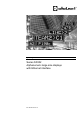
Operating instructions Series SX302 Alphanumeric large size displays with Ethernet interface BAL SX302 ETH EN 3.
MAC address: : : : : : Site of the unit: Germany Siebert Industrieelektronik GmbH Siebertstrasse, D-66571 Eppelborn Phone +49 (0) 6806 980-0, Fax +49 (0) 6806 980-999 www.siebert.de, info@siebert.de France Siebert France Sarl 33 rue Poincaré, BP 90 334, F-57203 Sarreguemines Cédex Phone +33 (0) 3 87 98 63 68, Fax +33 (0) 3 87 98 63 94 www.siebert.fr, info@siebert.
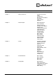
Table of contents Chapter 1 Safety precautions Important information Safety Intended use Mounting and installation Grounding EMC measures Disposal Chapter 2 Unit description Model designation Unit construction Display technology Principle circuit diagram Display range Central Processing Unit Parameterization Ethernet interface Function inputs Auxiliary voltage Menu display Menu buttons Switching output Status indicators Ethernet LEDs Power supply Chapter 3 Control Activation commands Network paramet
Chapter 6 Technical data Unit properties Max. Power consumption Switching output Screw clips Housing colors Front frame Ambient conditions Chapter 7 Unit measurements and weights Units with one-side display Units with double-sided display 4 BAL SX302 ETH EN 3.
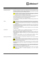
Chapter 1 Safety precautions Important information Read these operating instructions before starting the unit. They provide you with important information on the use, safety and maintenance of the units. This helps you to protect yourself and prevent damage to the unit. Information intended to help you to avoid death, bodily harm or considerable damage to property are highlighted by the warning triangle shown here; it is imperative that this information be properly heeded.
Grounding All devices are equipped with a metal housing. They comply with safety class I and require a protective earth connection. The connecting cable for the operating voltage must contain a protective earth wire of a sufficient cross section (DIN VDE 0106 part 1, DIN VDE 0411 part 1). EMC measures The devices comply with the EU Directive 89/336/EEC (EMC Directive) and provide the required interference immunity.
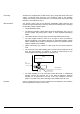
Chapter 2 Unit description Model designation The model designation of the units is: SX302-xx/xx/xx-xxx/xx-E0 x = The 'x's in the model designation indicate the size and design of the units (see Chapter 6). Unit construction The following figure shows model type S302-06/10/xx-xxx/xx-xx as example for the other model types. The front frame of the housing is locked with quick-action releases and can be hinged downward for opening the unit.
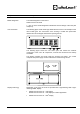
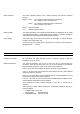
Principle circuit C8 C7 C6 C5 C4 C3 C2 C1 Central Processing Unit Ethernetconnection Power supply unit 10M RJ45 100M F2 Ethernet-Interface Display range F1 M P Function inputs/Auxiliary voltage NC NO CO Switching output L N PE Power supply Depending on the type, the units have the following displays: SX302-x1/xx/xx-xxx/xx-xx (1 digit): C1 SX302-x2/xx/xx-xxx/xx-xx (2 digits): C2…C1 SX302-x3/xx/xx-xxx/xx-xx (3 digits): C3…C1 SX302-x4/xx/xx-xxx/xx-xx (4 digits): C4…C1 SX302-x5/xx/xx
Parameterization The parameterization of the unit is done by means of a menu in the menu display (see chapter 4). Ethernet interface The Ethernet interface serves for activation of the devices (see chapter 4.
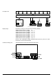
Status indicators The status indicators (LEDs) of the central processing unit have the following function: READY STAT: On = Ready for data transmission via Ethernet Off = Address conflict on the Ethernet DHCP: On = Ready for data transmission via Ethernet Off = No DHCP server found DATA Data are received OUT Switching output is active Ethernet-LEDs The data transmission rate is detected automatically and displayed via the 100M and 10M Ethernet LEDs.
Socket connection The units are set up as TCP server by default. The data is transmitted to port 8000 via a socket connection (factory settings). Other ports between 2000 and 9999 can be set in menu item P (see chapter 4). In menu item P, the decimal points of the port number flash one after the other. The digit with the decimal point flashing can be set to the value requested by means of the menu key [Q].
Brightness The brightness of the display can be reduced with the following command: Normal brightness: $L0 Reduced brightness: $L1 The brightness of the display can also be reduced with an H signal applied to functional input F2 (priority compared to the commands). For units provided with an LRD® display brightness reduction is not possible.
Chapter 4 Parameterization Menu The parameterization of the devices is carried out in a menu of the menu display. During normal operation On nE appears in the menu display as soon as data arrive at the Ethernet interface. Menu operation To reach the menu, press both menu buttons simultaneously (approx. 1 sec.) until an audible signal is heard and menu item 01 appears in the menu display.
Menu item IP IP-Address Settings Static DHCP* I1 IP-Address Byte 1 (xxx.- . . - -) 192.168.127.254* 0 L 255 192* L IP-Address Byte 2 (- - -.xxx.- . - -) 0 L 255 168* L IP-Address Byte 3 (- - -.- - -.xxx.- - -) 0 L 255 127* L IP-Address Byte 4 (- - -.- . - -.xxx) 1 L 254 254* L Subnet Mask Byte 1 (xxx.- . . - -) 255.255.255.0* 0 L 255 255* S L Subnet Mask Byte 2 (- - -.xxx.- . - -) 0 L 255 255* 0 L 255 255* 1 L 255 000* Standard-Gateway Byte 1 (xxx.- . . - -) 192.168.127.
Menu item R Switching output BAL SX302 ETH EN 3.
Chapter 5 Configuration MAC address The MAC address of the unit is to be found on the Ethernet coupling of the control processor (see label). It is possibly needed for commissioning and should be written down on page 2 of this operating manual before the unit is mounted on a hardly accessible location. Basic configuration The basic configuration can be set up without external aids via the menu (see chapter 4).
Chapter 6 Technical data Unit properties The model designation is structured as follows: SX302 1 digit 2 digits 3 digits 4 digits 5 digits 6 digits 7 digits 8 digits – / : 0 0 0 0 0 0 0 0 : 1 2 3 4 5 6 7 8 Character height of 50 mm Character height of 100 mm / : : : : : : : : : : 0 1 LED ® LRD : : : : : : : : : : 5 0 – : : : : : : : : : : : : : 0 4 Color of the characters red Color of the characters green Color of the characters white : : : : : : : : : : : : : : : : R G W Display readable on o
Max. power consumption Units with one-side display Units with double-sided display 1 digit SX302-01/10/0x-1xx/xx-xx SX302-01/10/4x-1xx/xx-xx approx. 12 VA approx. 50 VA 1 digit SX302-01/10/0x-2xx/xx-xx SX302-01/10/4x-2xx/xx-xx approx. 16 VA approx. 91 VA 2 digits SX302-02/05/0x-1xx/xx-xx SX302-02/10/0x-1xx/xx-xx SX302-02/10/4x-1xx/xx-xx approx. 12 VA approx. 15 VA approx. 50 VA 2 digits SX302-02/05/0x-2xx/xx-xx SX302-02/10/0x-2xx/xx-xx SX302-02/10/4x-2xx/xx-xx approx. 15 VA approx. 21 VA approx.
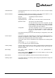
Chapter 7 Unit measurements and weights Units with one-side display The following figure shows unit version S302-04/10/4x-1xx/xx-xx, representing the other unit versions listed in the following table. BAL SX302 ETH EN 3.1 1 digit SX302-01/10/xx-1xx/xx-xx A 330 mm B 245 mm C 145 mm D 32 mm ø 7 mm Weight approx. 7 kg 2 digits SX302-02/05/xx-1xx/xx-xx SX302-02/10/xx-1xx/xx-xx 300 mm 330 mm 185 mm 245 mm 110 mm 145 mm 32 mm 32 mm 7 mm 7 mm approx. 5 kg approx.
Units with double-sided display The following figure shows unit version S302-04/10/4x-2xx/xx-xx, representing the other unit versions listed in the following table. Units with character height of 50 mm (SX302-xx/06/xx2xx/xx-xx) are provided with 2 eyes instead of 4. 20 1 digit SX302-01/10/xx-2xx/xx-xx A 330 mm B 245 mm C 240 mm Weight approx. 11 kg 2 digits SX302-02/05/xx-2xx/xx-xx SX302-02/10/xx-2xx/xx-xx 300 mm 330 mm 185 mm 245 mm 150 mm 240 mm approx. 9 kg approx.