Moxa EtherDevice Switch EDS-205A/208A Series Hardware Installation Guide Fourth Edition, October 2009 © 2009 Moxa Inc. All rights reserved. Reproduction without permission is prohibited.
Overview The EDS-205A/208A series of industrial Ethernet switches are entry-level industrial 5 and 8-port Ethernet switches that support IEEE 802.3, IEEE 802.3u, and IEEE 802.3x with 10/100M, full/half-duplex, and MDI/MDIX auto-sensing. The EDS-205A/208A series provides 12/24/48 VDC (9.6 to 60VDC)/18 to 30 VAC redundant power inputs that can be connected simultaneously to a live AC/DC power source.
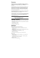
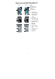
Panel Layout of EDS-205A/208A (Standard) EDS-205A Front Panel View EDS-208A Front Panel View 1. 2 5 6 2. 7 3. Grounding screw Terminal block for power input P1/P2 7 8 8 9 4. DIP Switches 5. Power input P1 LED 6. Power input P2 LED 7. 10/100BaseT(X) Port 8. Top Panel View TP port’s 10/100 Mbps LED Top Panel View 9. 3 1 1 Heat dissipation orifices Model Name 10. Screw hole for wall mounting kit 11.
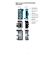
Panel Layout of EDS-205A-M-SC/ST EDS-205A-M-SC Front Panel View EDS-205A-M-ST Front Panel View NOTE: The appearance of 2 5 6 2 5 6 EDS-205A-S-SC is identical to EDS-205A-M-SC. 7 7 8 8 1. 2. 10 11 9 Grounding screw Terminal block for power input P1/P2 10 11 3. 9 Heat dissipation orifices Top Panel View Top Panel View 4. DIP Switches 5. Power input P1 LED 3 6. Power input P2 LED 1 1 7. 10/100BaseT(X) Port 2 2 3 8. TP port’s 10/100 Mbps LED 4 4 9. Model Name 10.
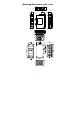
Panel Layout of EDS-208A-M-SC/ST EDS-208A-M-SC Front Panel View EDS-208A-M-ST Front Panel View 2 5 6 NOTE: 2 5 6 The appearance of EDS-208A-S-SC is 10 7 10 7 identical to 11 8 11 8 EDS-208A-M-SC. 1. 9 9 2. Grounding screw Terminal block for power input P1/P2 Top Panel View 3. Top Panel View Heat dissipation orifices 4. DIP Switches 1 1 5. Power input P1 LED 2 2 3 4 3 4 6. Power input P2 LED 7. 10/100BaseT(X) Port 8.
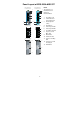
Panel Layout of EDS-208A-MM-SC/ST EDS-208A-MM-SC Front Panel View EDS-208A-MM-ST Front Panel View NOTE: 2 5 6 2 5 6 The appearance of EDS-208A-SS-SC is 10 7 10 7 identical to 11 8 11 8 EDS-208A-MM-SC. 1. 9 9 2. Grounding screw Terminal block for power input P1/P2 Top Panel View 3. Top Panel View Heat dissipation orifices 1 1 2 2 3 4 3 4 4. DIP Switches 5. Power input P1 LED 6. Power input P2 LED 7. 10/100BaseT(X) Port 8.
Mounting Dimensions (unit = mm) -7-
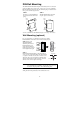
DIN-Rail Mounting The aluminum DIN-rail attachment plate should already be fixed to the back panel of the EDS when you take it out of the box. If you need to reattach the DIN-rail attachment plate, make sure the stiff metal spring is situated towards the top, as shown in the figures below. STEP 1: Insert the top of the DIN-Rail into the slot just below the stiff metal spring. STEP 2: The DIN-Rail attachment unit will snap into place as shown below.
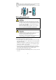
STEP 3: Once the screws are fixed on the wall, insert the four screw heads through the large parts of the keyhole-shaped apertures, and then slide the EDS-205A/208A downwards, as indicated. Tighten the four screws for added stability. ⇒ Wiring Requirements WARNING Safety First! Turn the power off before disconnecting modules or wires. The correct power supply voltage is listed on the product label. Check the voltage of your power source to make sure that you are using the correct voltage.
Grounding the EtherDevice Switch Grounding and wire routing help limit the effects of noise due to electromagnetic interference (EMI). Run the ground connection from the ground screw to the grounding surface prior to connecting devices. ATTENTION This product is intended to be mounted to a well-grounded mounting surface such as a metal panel.
MDI Port Pinouts Pin 1 2 3 6 MDI-X Port Pinouts Pin 1 2 3 6 Signal Tx+ TxRx+ Rx- 8-pin RJ45 Signal Rx+ RxTx+ Tx- 1 8 RJ45 (8-pin) to RJ45 (8-pin) Straight-Through Cable Wiring Straight-Through Cable Switch Port RJ45 Plug Pin 1 RJ45 Connector Tx+ TxRx+ Rx- NIC Port RJ45 Connector Cable Wiring 3 6 1 2 3 6 1 2 Rx+ RxTx+ Tx- RJ45 (8-pin) to RJ45 (8-pin) Cross-Over Cable Wiring Cross-Over Cable Switch Port (NIC Port) RJ45 Plug Pin 1 RJ45 Connector (Rx+) (Rx-) (Tx+) (Tx-) Tx+ TxRx+ Rx- Switch
ST-Port Pinouts ST-Port to ST-Port Cable Wiring A A B B Tx Cable Wiring Rx A B A B ATTENTION This is a Class 1 Laser/LED product. To avoid causing serious damage to your eyes, do not stare directly into the Laser Beam. Redundant Power Inputs Both power inputs can be connected simultaneously to live AC/DC power sources. If one power source fails, the other live source acts as a backup, and automatically supplies all of the EDS’s power needs.
LED Indicators The front panel of the Moxa EtherDevice Switch contains several LED indicators. The function of each LED is described in the table below. LED Color P1 AMBER P2 AMBER State On Off On Off On 10M 100M Yellow GREEN Description Power is being supplied to power input P1. Power is not being supplied to power input P1. Power is being supplied to power input P2. Power is not being supplied to power input P2. TP port’s 10 Mbps link is active. Blinking Data is being transmitted at 10 Mbps.
Switching and Address Learning The EDS has an address table that can hold up to 1024 addresses, which makes it suitable for use with large networks. The address tables are self-learning, so that as nodes are added or removed, or moved from one segment to another, the EDS automatically keeps up with new node locations. An address-aging algorithm causes the least-used addresses to be deleted in favor of newer, more frequently used addresses.
Power Input Voltage Input Current @ 24VDC 12/24/48 VDC (9.6 to 60 VDC), 18 to 30VAC (47 to 63 Hz) 0.1 A (EDS-205A) 0.11 A (EDS-205A-M/S) 0.13 A (EDS-208A) 0.17 A (EDS-208A-M/S) 0.22 A (EDS-208A-MM/SS) Removable 4-contact terminal block 1.
Technical Support Contact Information www.moxa.