Moxa EtherDevice Switch EDS-208 Series Hardware Installation Guide Second Edition, June 2008 © 2008 Moxa Inc., all rights reserved. Reproduction without permission is prohibited.
Overview The EDS-208 series of Moxa EtherDevice™ Switches are entry-level 8-port Ethernet Switches that provide a cost-effective solution for industrial Ethernet connections. EDS-208 provides a choice of 12 to 45 VDC power input or 18 to 30 VAC. The switches can operate reliably in a temperature range of -10 to 60°C, and the rugged hardware design makes EDS-208 perfect for ensuring that your Ethernet equipment can be used in demanding industrial environments.
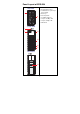
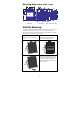
Panel Layout of EDS-208 Top View 1. Heat dissipation orifices 2. Terminal block for power input and grounding 1 3. Moxa Logo VV+ 2 24 VDC/VAC 4. Power input LED 5. 10/100BaseT(X) Port 6. TP port’s 100 Mbps LED 7. TP port’s 10 Mbps LED 8.
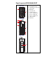
Panel Layout of EDS-208-M-SC/ST Top View Heat dissipation orifices 2. Terminal block for power input 3. Moxa Logo and grounding 1 VV+ 2 24 VDC/VAC 4. Power input LED 5. 10/100BaseT(X) Port 6. TP port’s 100 Mbps LED 7. TP port’s 10 Mbps LED 8. FX port’s 100 Mbps LED 9. 100BaseFX Port 10. DIN-Rail kit Front View 2 3 8 1.
Mounting Dimensions (unit = mm) 74 15 15 32 7 10.5 15.6 P P 40.03 100M Rx 23 7 7 8 5 6 8 Tx V- 4 5 24 VDC/VAC 3 100 1 2 V+ 6 74 3 100 76.2 100 12 4 100 1 10 2 10 40.03 86.5 EDS-208 Side View EDS-208-M-SC/ST Front View Rear View Top View DIN-Rail Mounting The plastic DIN-Rail attachment plate should already be fixed to the rear panel of EDS-208 when you take it out of the box.
Wiring Requirements ATTENTION Safety First! Be sure to disconnect the power cord before installing and/or wiring your EDS-208. Calculate the maximum possible current in each power wire and common wire. Observe all electrical codes dictating the maximum current allowable for each wire size. If the current goes above the maximum ratings, the wiring could overheat, causing serious damage to your equipment.
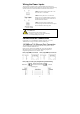
Wiring the Power Inputs The two left-most contacts of the 3-contact terminal block connector on EDS-208’s top panel are used for both the DC and AC inputs of EDS-208. Top and front views of one of the terminal block connectors are shown here. STEP 1: Insert the negative/positive DC or AC wires into the V-/V+ terminals. STEP 2: To keep the DC or AC wires from pulling loose, use a small flat-blade screwdriver to tighten the wire-clamp screws on the front of the terminal block connector.
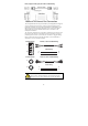
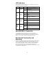
RJ45 (8-pin) to RJ45 (8-pin) Cross-Over Cable Wiring 100BaseFX Ethernet Port Connection The concept behind the SC/ST port and cable is quite straightforward. Suppose you are connecting devices I and II. Contrary to electrical signals, optical signals do not require a circuit in order to transmit data. Consequently, one of the optical lines is used to transmit data from device I to device II, and the other optical line is used to transmit data from device II to device I, for full-duplex transmission.
LED Indicators The front panel of EDS-208 contains several LED indicators. The function of each LED is described in the table below.
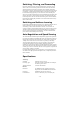
Switching, Filtering, and Forwarding Each time a packet arrives at one of the switched ports, a decision is made either to filter or to forward the packet. Packets with source and destination addresses belonging to the same port segment will be filtered, constraining those packets to one port, and relieving the rest of the network from the need to process them.
Optical Fiber Multi mode Distance 5 km Wavelength, nm 1300 Min. TX Output, dBm -20 Max.
Technical Support Contact Information www.moxa.