Moxa EtherDevice™ Switch EDS-510A Series User’s Manual www.moxa.com/product First Edition, October 2006 Moxa Networking Co., Ltd. Tel: +886-2-2910-1230 Fax: +886-2-2910-1231 Web: www.moxa.com Moxa Technical Support support@moxanet.tw Worldwide: support@usa.moxa.
Moxa EtherDevice™ Switch EDS-510A Series User’s Manual The software described in this manual is furnished under a license agreement and may be used only in accordance with the terms of that agreement. Copyright Notice Copyright © 2006 Moxa Networking Co., Ltd. All rights reserved. Reproduction without permission is prohibited. Trademarks Moxa is a registered trademark of the Moxa Group. All other trademarks or registered marks in this manual belong to their respective manufacturers.
Table of Contents Chapter 1 Introduction ...............................................................................................1-1 Overview .............................................................................................................................. 1-2 Package Checklist................................................................................................................. 1-2 Features .......................................................................................
Sample Applications of VLANs using Moxa EDS-510A ....................................... 3-39 Configuring Virtual LAN........................................................................................ 3-40 Using Multicast Filtering.................................................................................................... 3-43 The Concept of Multicast Filtering ......................................................................... 3-43 Configuring IGMP Snooping ..............................
1 Chapter 1 Introduction Welcome to Moxa EtherDevice Switch EDS-510A Series, the Gigabit Managed Redundant Ethernet Switch designed specially for connecting Ethernet-enabled devices in industrial field applications.
EDS-510A Series User’s Manual Introduction Overview As the world’s network and information technology becomes more mature, the trend is to use Ethernet as the major communications interface in many industrial communications and automation applications. In fact, a whole new industry has sprung up to provide Ethernet products that comply with the requirements of demanding industrial applications. The EDS-510A comes equipped with 3 gigabit Ethernet ports.
EDS-510A Series User’s Manual y y y y y y y Introduction Bandwidth management to prevent unpredictable network status Lock port for allowing access to authorized MAC addresses only Port mirroring for online debugging Automatic warning by exception through email, relay output Digital inputs to integrate a sensor and alarm with an IP network Automatic recovery of connected device IP addresses Line-swap fast recovery Useful Utility and Remote Configuration y y Configurable using a Web browser, Telnet/Seria
2 Chapter 2 Getting Started This chapter explains how to access the EDS-510A for the first time. There are three ways to access the switch: serial console, Telnet console, and web browser. The serial console connection method, which requires using a short serial cable to connect the EDS-510A to a PC’s COM port, can be used if you do not know the EDS-510A’s IP address. The Telnet console and web browser connection methods can be used to access the EDS-510A over an Ethernet LAN, or over the Internet.
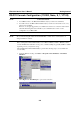
EDS-510A Series User’s Manual Getting Started RS-232 Console Configuration (115200, None, 8, 1, VT100) NOTE NOTE Connection Caution! 1. You cannot connect to the EDS-510A simultaneously by serial console and Telnet. 2. You can connect to the EDS-510A simultaneously by web browser and serial console, or by web browser and Telnet. However, we strongly suggest that you do NOT use more than one connection method at the same time.
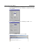
EDS-510A Series User’s Manual Getting Started 3. The Communication Parameter page of the Property window opens. Select the appropriate COM port for Console Connection, 115200 for Baud Rate, 8 for Data Bits, None for Parity, and 1 for Stop Bits. 4. Click the Terminal tab, and select VT100 for Terminal Type. Click OK to continue. 5. Type 1 to select ansi/VT100 terminal type, and then press Enter.
EDS-510A Series User’s Manual Getting Started 6. The Console login screen will appear. Press Enter to open the Account pop-up selector and then select either admin or user. Use the keyboard’s down arrow to move the cursor to the Password field, enter the Console Password (this is the same as the Web Browser password; leave the Password field blank if a console password has not been set), and then press Enter. 7. The EDS-510A’s Main Menu will be displayed.
EDS-510A Series User’s Manual Getting Started Configuration using a Telnet Console You may use Telnet to access the EDS-510A’s console utility over a network. To be able to access the EDS’s functions over the network (by Telnet or web browser) from a PC host that is connected to the same LAN as the EDS-510A, you need to make sure that the PC host and the EDS-510A are on the same logical subnet. To do this, check your PC host’s IP address and subnet mask. By default, the EDS-510A’s IP address is 192.168.
EDS-510A Series User’s Manual NOTE Getting Started 4. When the Main Menu of the EDS-510A’s console utility opens, click Terminal Æ preferences… from the menu at the top of the window. 5. When the Terminal Preferences window opens, make sure that the VT100 Arrows option is selected. The Telnet Console looks and operates in precisely the same manner as the RS-232 Console.
EDS-510A Series User’s Manual Getting Started Perform the following steps to access the EDS-510A’s web browser interface. NOTE 1. Open Internet Explorer and type EDS-510A’s IP address in the Address field. Press Enter to establish the connection. 2. The web login page will open. Select the login account (Admin or User) and enter the Password (this is the same as the Console password), and then click Login to continue. Leave the Password field blank if a password has not been set.
EDS-510A Series User’s Manual Getting Started Disabling Telnet and Browser Access If you are connecting the EDS-510A to a public network, but do not intend to use its management functions over the network, we suggest using the RS-232 console’s Basic Settings Æ System Info page to disable both Telnet Console and Web Configuration, as shown in the following figure.
3 Chapter 3 Featured Functions In this chapter, we explain how to access the EDS-510A’s configuration options, perform monitoring, and use administration functions. There are three ways to access these functions: RS-232 console, Telnet console, and web browser. The serial console connection method, which requires using a short serial cable to connect the EDS-510A to a PC’s COM port, can be used if you do not know the EDS-510A’s IP address.
EDS-510A Series User’s Manual Featured Functions Configuring Basic Settings The Basic Settings group includes the most commonly used settings required by administrators to maintain and control EDS-510A. System Identification The system identification items are displayed at the top of the web page, and will be included in alarm emails. Entering the system identification information makes it easier to identify the different switches connected to your network. Switch Name Setting Max.
EDS-510A Series User’s Manual Featured Functions Password The EDS-510A provides two levels of access privilege: admin privilege gives read/write access to all EDS-510A configuration parameters, and user privilege provides read access only. You will be able to view the configuration, but will not be able to make modifications. ATTENTION The EDS-510A’s default Password is not set (i.e., is blank).
EDS-510A Series User’s Manual Featured Functions Accessible IP The EDS-510A uses an IP address-based filtering method to control access to the EDS-510A units. Accessible IP Settings allows you to add or remove “Legal” remote host IP addresses to prevent unauthorized access. Access to the EDS-510A is controlled by IP address. If a host’s IP address is in the accessible IP table, then the host will be allowed access to the EDS-510A.
EDS-510A Series User’s Manual Featured Functions Port Port settings are included to give the user control over Port Access, Port Transmission Speed, Flow Control, and Port Type (MDI or MDIX). An explanation of each configuration item follows: Enable Setting checked unchecked Description Allows data transmission through the port. Immediately shuts off port access.
EDS-510A Series User’s Manual Featured Functions Speed Setting Auto 100M-Full 100M-Half 10M-Full 10M-Half Description Factory Default Allows the port to use the IEEE 802.3u protocol to negotiate with connected devices. The port and connected devices will determine the best speed for that connection. Auto Choose one of these fixed speed options if the opposing Ethernet device has trouble auto-negotiating line speed.
EDS-510A Series User’s Manual Featured Functions Auto IP Configuration Setting Disable By DHCP By BOOTP Description Factory Default Set up the EDS-510A’s IP address manually. The EDS-510A’s IP address will be assigned Disable automatically by the network’s DHCP server. The EDS-510A’s IP address will be assigned automatically by the network’s BOOTP server. Switch IP Address Setting IP Address of the EDS-510A Description Factory Default Identifies the EDS-510A on a TCP/IP network. 192.168.127.
EDS-510A Series User’s Manual Featured Functions Time The EDS-510A has a time calibration function based on information from an NTP server or user specified Time and Date information. Functions such as Auto warning “Email” can add real-time information to the message. NOTE The EDS-510A does not have a real time clock.
EDS-510A Series User’s Manual NOTE Featured Functions Changing the time zone will automatically correct the current time. You should configure the time zone before setting the time. Time Server IP/Name Setting 1st Time Server IP/Name 2nd Time Server IP/Name Description IP or Domain address (e.g., 192.168.1.1 or time.stdtime.gov.tw or time.nist.gov). The EDS-510A will try to locate the 2nd NTP Server if the 1st NTP Server fails to connect.
EDS-510A Series User’s Manual Featured Functions EDS-510A Series DIP Switches 1 ------ 2 MASTER 3 COUPLER 4 TURBO RING DIP Switch The default setting for each DIP Switch is OFF. The following table explains the effect of setting the DIP Switch to the ON position. Setting Description ------ Serves no function (reserved for future use). ON MASTER Enables the EDS-510A to be the Ring Master in a Turbo Ring topology, and enables the Turbo Ring break warning.
EDS-510A Series User’s Manual Featured Functions NOTE The Turbo Ring Ports and Coupling Ports will be added to all VLANs if you enable the “Turbo Ring DIP Switch” and set Turbo Ring DIP Switch from OFF to ON. NOTE If you enable the Hardware DIP Switch for Turbo Ring and set the Turbo Ring DIP Switch from ON to OFF, then the Ring Ports and Coupling Ports which are added to all VLANs are restored to their previous software settings. (For details on how to do this, please refer to “Using Virtual LAN.
EDS-510A Series User’s Manual Featured Functions After setting up the desired path and file name, click Activate to save the setting, and then click Download to download the prepared file from the remote TFTP server, or click Upload to upload the desired file to the remote TFTP server. System File Update—By Local Import/Export Configuration File To export the configuration file of this EDS-510A, click Export to save it to the local host.
EDS-510A Series User’s Manual Featured Functions Auto load system configurations when system boots up Setting Enable Disable Description Enables Auto load system configurations when system boots up Disables Auto load system configurations when system boots up Factory Default Enable Save the current configurations to ABC To export the current configuration file of the EDS-510A, click on Save to save it to the ABC.
EDS-510A Series User’s Manual Featured Functions the other seven ports will provide back up and share the traffic automatically. Port trunking can be used to combine up to 8 ports between two EDS-510A switches. If all ports on both switch units are configured as 100BaseTX and they are operating in full duplex, the potential bandwidth of the connection will be 800 Mbps.
EDS-510A Series User’s Manual Featured Functions Configuring Port Trunking The Port Trunking Settings page is used to assign ports to a Trunk Group. Step 1: Step 2: Step 3: Step 4: Select Trk1, Trk2, Trk3, or Trk4 from the Trunk Group drop-down box. Select Static, or LACP from the Trunk Type drop-down box. Under Member Ports and Available Ports, select the specific ports. Use the Up / Down buttons to add/remove designated ports to/from a trunk group.
EDS-510A Series User’s Manual Featured Functions Available Ports/Member Port Setting Member/Available Ports Check box Port Port description Name Speed FDX Flow Control Up Down Description Use Up/Down buttons to add/remove specific ports from available ports to/from trunk group. Check to designate which ports to add or remove. Port number Displays the media type for each module’s port Max.
EDS-510A Series User’s Manual Protocol Version UI Setting V1, V2c Read SNMP V1, Community V2c V1, V2c Write/Read Community No-Auth Featured Functions Authentication Type Data Encryption Method Community string No Use a community string match for authentication Community string No Use a community string match for authentication No Use account with admin or user to access objects Provides authentication based on HMAC-MD5, or HMAC-SHA No algorithms.
EDS-510A Series User’s Manual Featured Functions only allows reading the MIB file, but does not have authorization to write. Admin Auth. Type (for SNMP V1, V2c, V3, and V3 only) Setting No-Auth MD5-Auth SHA-Auth Description Use admin. account to access objects. No authentication Provide authentication based on the HMAC-MD5 algorithms. 8-character passwords are the minimum requirement for authentication. Provide authentication based on the HMAC-SHA algorithms.
EDS-510A Series User’s Manual Featured Functions 1st Trap Community Setting character string Description Use a community string match for authentication (maximum of 30 characters). Factory Default public 2nd Trap Server IP/Name Setting IP or Name Description Enter the IP address or name of the 2nd Trap Server used by your network. Factory Default None 2nd Trap Community Setting character string Description Use a community string match for authentication (maximum of 30 characters).
EDS-510A Series User’s Manual Featured Functions Ring, if any segment of the network gets disconnected, your automation system will be back to normal in less than 300 ms. NOTE Port trunking and Turbo Ring can be enabled simultaneously to form a backbone. Doing so will increase the bandwidth of the backbone, and also provide redundancy.
EDS-510A Series User’s Manual Featured Functions When the number of EDS-510A units in the Turbo Ring is even. If there are 2N EDS-510A units (an even number) in the Turbo Ring, then the backup segment is one of the two segments connected to the (N+1)st EDS-510A (i.e., the EDS-510A unit directly opposite the Master). Master When the number of EDS-510A units in the Turbo Ring is odd.
EDS-510A Series User’s Manual Featured Functions Ring Coupling Switch B Switch D Main Path Coupling Control Port Backup Path Coupling Port Switch A: "Coupler" Switch C To support the Ring Coupling function, select two EDS-510A (e.g., Switch A and B in the above figure) in the Turbo Ring and another two EDS-510A in the adjacent Turbo Ring (e.g., Switch C and D). Decide appropriate coupling ports in each switch and link them together. Next, assign one switch (e.g.
EDS-510A Series User’s Manual Featured Functions Configuring Turbo Ring Use the Communication Redundancy page to configure Turbo Ring. Now Active This field shows which communication protocol is in use: Turbo Ring, RSTP, or neither. Master/Slave This field appears only when Turbo Ring mode is selected for Redundancy Protocol. It indicates if this EDS-510A is or is not the Master of the Turbo Ring.
EDS-510A Series User’s Manual Featured Functions Redundancy Protocol Setting Turbo Ring RSTP (IEEE 802.1W/1D) Description Select this item to change to the Turbo Ring configuration page. Select this item to change to the RSTP configuration page. Factory Default None None Set as Master Setting Enable/Disable Description Select this EDS-510A as Master Factory Default None Redundant Ports Setting Description Factory Default 1st Port Select any port of EDS-510A to be one of the redundant ports.
EDS-510A Series User’s Manual NOTE Featured Functions The STP protocol is part of the IEEE Std 802.1D, 1998 Edition bridge specification. The following explanation uses bridge instead of switch. What is STP? STP (802.1D) is a bridge-based system that is used to implement parallel paths for network traffic. STP uses a loop-detection process to: y y Locate and then disable less efficient paths (i.e., paths that have a lower bandwidth).
EDS-510A Series User’s Manual Featured Functions What happens if a link failure is detected? As shown in next figure, the STP process reconfigures the network so that traffic from LAN segment 2 flows through Bridge B. LAN 1 Bridge B Bridge A LAN 2 Bridge C LAN 3 STP will determine which path between each bridged segment is most efficient, and then assigns a specific reference point on the network. When the most efficient path has been identified, the other paths are blocked.
EDS-510A Series User’s Manual y y y y Featured Functions Which bridge should be the Root Bridge. The Root Bridge is the central reference point from which the network is configured. The Root Path Costs for each bridge. This is the cost of the paths from each bridge to the Root Bridge. The identity of each bridge’s Root Port. The Root Port is the port on the bridge that connects to the Root Bridge via the most efficient path.
EDS-510A Series User’s Manual Featured Functions LAN Segment 1 Port 1 (Root Port) Port 1 (Designated Bridge Port) Bridge A Port 1 (Root Port) Cost =100 Cost =100 Bridge B Bridge X Port 2 (Blocked Port) Port 2 (Designated Bridge Port) Port 2 (Root Bridge) LAN Segment 2 Port 1 (Root Port) Port 1 (Root Port) Cost =100 Cost =200 Bridge C Bridge Y Port 2 (Designated Bridge Port) Port 2 (Blocked Port) LAN Segment 3 y y y y y y Bridge A has been selected as the Root Bridge, since it was dete
EDS-510A Series User’s Manual Featured Functions Switch A 100BaseTX full-duplex Link; only carries VLAN1 (path cost = 18) VLAN1 VLAN2 Switch B VLAN1 VLAN2 100BaseTX full-duplex Link; only carries VLAN2 (path cost = 18) Switch C Block 802.1Q tagged, 10BaseTx half-duplex Link carries VLAN1, 2 (path cost = 100) VLAN1 VLAN2 To avoid subdividing VLANs, all inter-switch connections should be made members of all available 802.1Q VLANs. This will ensure connectivity at all times.
EDS-510A Series User’s Manual Featured Functions At the bottom of this page, the user can configure the “Settings” of this function. For RSTP, you can configure: Protocol of Redundancy Setting Turbo Ring RSTP (IEEE 802.1W/1D) Description Select this item to change to the Turbo Ring configuration page. Select this item to change to the RSTP configuration page. Factory Default None Description Increase this device’s bridge priority by selecting a lower number.
EDS-510A Series User’s Manual NOTE Featured Functions We suggest not enabling the Spanning Tree Protocol once the port is connected to a device (PLC, RTU, etc.) as opposed to network equipment. The reason is that it will cause unnecessary negotiation. Port Priority Setting Numerical value selected by user Description Increase this port’s priority as a node on the Spanning Tree topology by entering a lower number.
EDS-510A Series User’s Manual Featured Functions Using Traffic Prioritization EDS-510A’s traffic prioritization capability provides Quality of Service (QoS) to your network by making data delivery more reliable. You can prioritize traffic on your network to ensure that high priority data is transmitted with minimum delay. Traffic can be controlled by a set of rules to obtain the required Quality of Service for your network.
EDS-510A Series User’s Manual IEEE 802.1p Priority Level 0 1 2 3 4 5 6 7 Featured Functions IEEE 802.1D Traffic Type Best Effort (default) Background Standard (spare) Excellent Effort (business critical) Controlled Load (streaming multimedia) Video (interactive media); less than 100 milliseconds of latency and jitter Voice (interactive voice); less than 10 milliseconds of latency and jitter Network Control Reserved traffic Even though the IEEE 802.
EDS-510A Series User’s Manual 2. Featured Functions As the 802.1p priority levels are fixed to the traffic queues, the packet will be placed in the appropriate priority queue, ready for transmission through the appropriate egress port. When the packet reaches the head of its queue and is about to be transmitted, the device determines whether or not the egress port is tagged for that VLAN. If it is, then the new 802.1p tag is used in the extended 802.1D header.
EDS-510A Series User’s Manual Featured Functions Moxa EDS-510A supports inspection of layer 3 TOS and/or layer 2 CoS tag information to determine how to classify traffic packets. Queuing Mechanism Setting Weighted Fair Strict Description EDS-510A has 4 priority queues. In the weighted fair scheme, an 8, 4, 2, 1 weighting is applied to the four priorities.
EDS-510A Series User’s Manual Featured Functions CoS Mapping Setting Low/Normal/ Medium/High Description Set the mapping table of different CoS values to 4 different egress queues. Factory 0: Low 1: Low 2: Normal 3: Normal 4: Medium 5: Medium 6: High 7: High TOS/DiffServ Mapping Setting Low/Normal/ Medium/High Description Set the mapping table of different TOS values to 4 different egress queues.
EDS-510A Series User’s Manual Featured Functions Using Virtual LAN Setting up Virtual LANs (VLANs) on your EDS-510A increases the efficiency of your network by dividing the LAN into logical segments, as opposed to physical segments. In general, VLANs are easier to manage. The Virtual LAN (VLAN) Concept What is a VLAN? A VLAN is a group of devices that can be located anywhere on a network, but which communicate as if they are on the same physical segment.
EDS-510A Series User’s Manual y y Featured Functions VLANs provide extra security: Devices within each VLAN can only communicate with other devices on the same VLAN. If a device on VLAN Marketing needs to communicate with devices on VLAN Finance, the traffic must pass through a routing device or Layer 3 switch. VLANs help control traffic: With traditional networks, congestion can be caused by broadcast traffic that is directed to all network devices, regardless of whether or not they need it.
EDS-510A Series User’s Manual y y Featured Functions Access Port: The port connects to a single device that is not tagged. The user must define the default port PVID that determines to which VLAN the device belongs. Once the ingress packet of this Access Port egresses to another Trunk Port (the port needs all packets to carry tag information), the EDS-510A will insert this PVID into this packet to help the next 802.1Q VLAN switch recognize it.
EDS-510A Series User’s Manual Featured Functions y Port 6 connect a single untagged device and assigns it to VLAN 5; it should be configured as “Access Port” with PVID 5. y Port 7 connects a single untagged device and assigns it to VLAN 4; it should be configured as “Access Port” with PVID 4. After proper configuration: y y y y Packets from device A will travel through “Trunk Port 3” with tagged VID 5.
EDS-510A Series User’s Manual Featured Functions VLAN Mode Setting Description 802.1Q VLAN Set VLAN mode to 802.1Q VLAN Port-based VLAN Set VLAN mode to Port-based VLAN Factory Default 802.1Q VLAN Management VLAN ID Setting VLAN ID ranges from 1 to 4094 Description Set the management VLAN of this EDS-510A. Factory Default 1 Port Type Setting Access Trunk Description This port type is used to connect single devices without tags. Select “Trunk” port type to connect another 802.
EDS-510A Series User’s Manual Featured Functions To configure the EDS-510A’s Port-based VLAN, use the VLAN Setting page to configure the ports. VLAN Mode Setting Description 802.1Q VLAN Set VLAN mode to 802.1Q VLAN Port-based VLAN Set VLAN mode to Port-based VLAN Factory Default 802.1Q VLAN Port Setting Enable/Disable Description Set port to specific VLAN Group. Factory Default Enable (all ports belong to VLAN1) VLAN Table In 802.
EDS-510A Series User’s Manual NOTE Featured Functions The physical network can have a maximum of 64 VLAN settings. Using Multicast Filtering Multicast filtering improves the performance of networks that carry multicast traffic. This section explains multicasts, multicast filtering, and how multicast filtering can be implemented on your EDS-510A. The Concept of Multicast Filtering What is an IP Multicast? A multicast is a packet sent by one host to multiple hosts.
EDS-510A Series User’s Manual Featured Functions Network without multicast filtering Group 1 Multicast Stream Group 2 Multicast Stream Serial ports Console IGMP Group2 LAN 1 IGMP Group1 2 3 4 5 6 7 8 9 10 11 12 13 14 15 16 IGMP Group2 IGMP Group1 All hosts receive the multicast traffic, even if they don’t need it.
EDS-510A Series User’s Manual Featured Functions Query Mode Query mode allows the EDS-510A to work as the Querier if it has the lowest IP address on the subnetwork to which it belongs. IGMP querying is enabled by default on the EDS-510A to help prevent interoperability issues with some multicast routers that may not follow the lowest IP address election method. Enable query mode to run multicast sessions on a network that does not contain IGMP routers (or queriers).
EDS-510A Series User’s Manual Featured Functions Configuring IGMP Snooping IGMP Snooping provides the ability to prune multicast traffic so that it travels only to those end destinations that require that traffic, thereby reducing the amount of traffic on the Ethernet LAN. IGMP Snooping Settings IGMP Snooping Enable Setting Enable/Disable Description Factory Default Select the option to enable the IGMP Snooping function Disabled globally.
EDS-510A Series User’s Manual NOTE Featured Functions At least one switch must be designated the Querier or enable IGMP snooping and GMRP when enabling Turbo Ring and IGMP snooping simultaneously. IGMP Table The EDS-510A displays the current active IGMP groups that were detected. The information includes VID, Auto-learned Multicast Router Port, Static Multicast Router Port, Querier Connected Port, and the IP and MAC addresses of active IGMP groups.
EDS-510A Series User’s Manual Featured Functions Configuring GMRP GMRP is a MAC-based multicast management protocol, whereas IGMP is IP-based. GMRP provides a mechanism that allows bridges and end stations to register or un-register Group membership information dynamically.
EDS-510A Series User’s Manual Featured Functions Traffic Rate Limiting Settings Ingress Setting Ingress rate Description Factory Default Select the ingress rate for all packets from the following N/A options: not limited, 3%, 5%, 10%, 15%, 25%, 35%, 50%, 65%, 85% Using Port Access Control The EDS-510A provides two kinds of Port-Based Access Controls. One is Static Port Lock and the other is IEEE 802.1X.
EDS-510A Series User’s Manual Featured Functions The EDS-510A acts as an authenticator in the 802.1X environment. A supplicant and an authenticator exchange EAPOL (Extensible Authentication Protocol over LAN) frames with each other. We can either use an external RADIUS server as the authentication server, or implement the authentication server in the EDS-510A by using a Local User Database as the authentication look-up table.
EDS-510A Series User’s Manual 5. 6. 7. Featured Functions The supplicant responds to the “EAP Request/MD5-Challenge” by sending an “EAP Response/MD5-Challenge” frame that encapsulates the user’s password using the MD5 hash algorithm.
EDS-510A Series User’s Manual Featured Functions Database Option Setting Local (Max. 32 users) Radius Radius, Local Description Factory Default Select this option when setting the Local User Database Local as the authentication database. Select this option to set an external RADIUS server as Local the authentication database. The authentication mechanism is “EAP-MD5.” Select this option to make an external RADIUS server as Local the authentication database with first priority.
EDS-510A Series User’s Manual Featured Functions 802.1X Re-Authentication The EDS-510A can force connected devices to be re-authorized manually. 802.1X Re-Authentication Setting Enable/Disable Description Select the option to enable 802.1X Re-Authentication Factory Default Disable Local User Database Setup When setting the Local User Database as the authentication database, set the database first. Local User Database Setup Setting User Name (Max. 30 characters) Password (Max.
EDS-510A Series User’s Manual Description (Max. 30 characters) NOTE Featured Functions Description for Local User Database None The user name for the Local User Database is case-insensitive. Port Access Control Table The port status will indicate whether the access is authorized or unauthorized. Using Auto Warning Since industrial Ethernet devices are often located at the endpoints of a system, these devices will not always know what is happening elsewhere on the network.
EDS-510A Series User’s Manual Featured Functions Event Type Event Types can be divided into two basic groups: System Events and Port Events. System Events are related to the overall function of the switch, whereas Port Events are related to the activity of a specific port. System Events Warning e-mail is sent when… Switch Cold Start Switch Warm Start Power is cut off and then reconnected. The EDS-510A is rebooted, such as when network parameters are changed (IP address, subnet mask, etc.).
EDS-510A Series User’s Manual Featured Functions that port (provided this item is Enabled). Traffic-Threshold (%) Enter a non-zero number if the port’s Traffic-Overload item is Enabled. Traffic-Duration (sec.) A Traffic-Overload warning is sent every Traffic-Duration seconds if the average Traffic-Threshold is surpassed during that time period. NOTE The Traffic-Overload, Traffic-Threshold (%), and Traffic-Duration (sec.) Port Event items are related.
EDS-510A Series User’s Manual change Password Old Password New Password Retype Password Featured Functions click the Change password check-box, type the Old Password, type the New Password, retype the New password, and then click Activate; Max. 45 Characters. Type the current password when changing the password None Type new password when enabled to change password; None Max. 45 Characters.
EDS-510A Series User’s Manual Featured Functions Event Types can be divided into two basic groups: System Events and Port Events. System Events are related to the overall function of the switch, whereas Port Events are related to the activity of a specific port. The EDS-510A supports two relay outputs. You can configure which relay output is related to which events. This helps administrators identify the importance of the different events.
EDS-510A Series User’s Manual NOTE Featured Functions The Traffic-Overload, Traffic-Threshold (%), and Traffic-Duration (sec) Port Event items are related. If you Enable the Traffic-Overload event, then be sure to enter a non-zero Traffic-Threshold percentage, as well as a Traffic-Duration between 1 and 300 seconds. Override relay alarm settings Select this option to override the relay warning setting temporarily.
EDS-510A Series User’s Manual Featured Functions effect, the EDS-510A acts as a DHCP server by assigning a connected device with a specific IP address stored in its internal memory. Each time the connected device is switched on or rebooted, the EDS-510A sends the device the desired IP address.
EDS-510A Series User’s Manual Featured Functions Desired IP Address Setting IP Address Description Set the desired IP of connected devices. Factory Default None Using Diagnosis The EDS-510A provides two important tools for administrators to diagnose network systems. Mirror Port The Mirror port function can be used to monitor data being transmitted through a specific port.
EDS-510A Series User’s Manual Featured Functions Ping The Ping function uses the ping command to give users a simple but powerful tool for troubleshooting network problems. The function’s most unique feature is that even though the ping command is entered from the user’s PC keyboard, the actual ping command originates from the EDS-510A itself. In this way, the user can essentially control the EDS-510A and send ping commands out through its ports.
EDS-510A Series User’s Manual Featured Functions Monitor by Port Access the Monitor by Port function by selecting ALL 10/100M or 1G Ports or Port i, in which i= 1, 2, …, G2, from the left pull-down list. The Port i options are identical to the Monitor by System function discussed above, in that users can view graphs that show All Packets, TX Packets, RX Packets, or Error Packets activity, but in this case, only for an individual port.
EDS-510A Series User’s Manual Featured Functions The table will display the following information: MAC Type Port This field shows the MAC address This field shows the type of this MAC address This field shows the port that this MAC address belongs to Using Event Log Bootup Date Time System Startup Time Events NOTE This field shows how many times the EDS-510A has been rebooted or cold started. The date is updated based on how the current date is set in the “Basic Setting” page.
EDS-510A Series User’s Manual Featured Functions Using Syslog This function provides the event logs for the syslog server. The function supports 3 configurable syslog servers and syslog server UDP port numbers. When an event occurs, the event will be sent as a syslog UDP packet to the specified syslog servers.
EDS-510A Series User’s Manual 3. NOTE Featured Functions Select Yes to enter the EDS-510A’s web browser interface and access the web browser interface secured via HTTPS/SSL. Moxa provides a Root CA certificate .After installing this certificate into your PC or notebook, you can access the web browser interface directly and will not see any warning messages again. You may download the certificate from the EDS-510A’s CD-ROM.
4 Chapter 4 EDS Configurator GUI EDS Configurator is a comprehensive Windows-based GUI that is used to configure and maintain multiple EDS-510A switches.
EDS-510A Series User’s Manual EDS Configurator GUI Starting EDS Configurator To start EDS Configurator, locate and then run the executable file edscfgui.exe. NOTE You may download the EDS Configurator software from Moxa’s website at www.moxa.com. For example, if the file was placed on the Windows desktop, it should appear as follows. Simply double click on the icon to run the program. The Moxa EtherDevice Server Configurator window will open, as shown below.
EDS-510A Series User’s Manual EDS Configurator GUI Once the search is complete, the Configurator window will display a list of all switches that were located. Search by IP address This utility is used to search for EDS-510A switches one at a time. Note that the search is conducted by IP address, so you should be able to locate any EDS-510A that is properly connected to your LAN, WAN, or even the Internet.
EDS-510A Series User’s Manual EDS Configurator GUI Upgrade Firmware Keep your EDS-510A up to date with the latest firmware from Moxa. Perform the following steps to upgrade the firmware: 1. 2. Download the updated firmware (*.rom) file from the Moxa website (www.moxa.com). Click the switch (from the Moxa EtherDevice Server Configurator window) whose firmware you wish to upgrade to highlight it. 3. Click the Upgrade Firmware toolbar icon , or select Upgrade under the Firmware menu.
EDS-510A Series User’s Manual EDS Configurator GUI Export Configuration The Export Configuration utility is used to save the entire configuration of a particular EDS-510A to a text file. Take the following steps to export a configuration: 1. Highlight the switch (from the Server list in the Configurator window’s left pane), and then click the Export toolbar icon or select Export Configuration from the Configuration menu.
EDS-510A Series User’s Manual 3. EDS Configurator GUI You may use a standard text editor, such as Notepad under Windows, to view and modify the newly created configuration file. Import Configuration The Import Configuration function is used to import an entire configuration from a text file to the EDS-510A.
EDS-510A Series User’s Manual EDS Configurator GUI 3. The Setup Configuration window will be displayed, with a special note attached at the bottom. Parameters that have been changed will be activated with a checkmark. You may make more changes if necessary, and then click OK to accept the changes. 4. Click Yes in response to the following warning message to accept the new settings.
EDS-510A Series User’s Manual y y y EDS Configurator GUI Fixed The EDS-510A is not password protected, and “Search by IP address” was used to locate it manually. Locked Fixed The EDS-510A is password protected, “Search by IP address” was used to locate it manually, and the password has not yet been entered from within the current Configurator session.
A Appendix A MIB Groups The EDS-510A comes with built-in SNMP (Simple Network Management Protocol) agent software that supports cold/warm start trap, line up/down trap, and RFC 1213 MIB-II. The standard MIB groups that the EDS-510A series support are: MIB II.1 – System Group sysORTable MIB II.2 – Interfaces Group ifTable MIB II.4 – IP Group ipAddrTable ipNetToMediaTable IpGroup IpBasicStatsGroup IpStatsGroup MIB II.5 – ICMP Group IcmpGroup IcmpInputStatus IcmpOutputStats MIB II.
EDS-510A Series User’s Manual MIB Groups MIB II.10 – Transmission Group dot3 dot3StatsTable MIB II.11 – SNMP Group SnmpBasicGroup SnmpInputStats SnmpOutputStats MIB II.
EDS-510A Series User’s Manual MIB Groups The EDS-510A also provides a private MIB file, located in the file “Moxa-EDS510A-MIB.my” on the EDS-510A Series utility CD-ROM. Public Traps: 1. Cold Start 2. Link Up 3. Link Down 4. Authentication Failure 5. dot1dBridge New Root 6. dot1dBridge Topology Changed Private Traps: 1. Configuration Changed 2. Power On 3. Power Off 4. Traffic Overloaded 5. Turbo Ring Topology Changed 6. Turbo Ring Coupling Port Changed 7.
B Appendix B Technology Standards Protocols MIB Interface RJ45 Ports Fiber Ports Console LED Indicators Alarm Contact Digital Input Specifications IEEE802.3, 802.3u, 802.3x, 802.1D, 802.1w, 802.1Q, 802.1p IGMP V1/V2/V3 device, GVRP, SNMP V1/V2c/V3, DHCP Server/Client, BOOTP, TFTP, SNTP, SMTP, RARP and EDS-SNMP OPC server Pro (Optional) MIB-II, Ethernet-Like MIB, P-BRIDGE MIB, Q-BRIDGE MIB, Bridge MIB, RSTP MIB, RMON MIB Group 1,2.
EDS-510A Series User’s Manual Power Input Voltage Input Current (@24V) Connection Overload Current Protection Reverse Polarity Protection Mechanical Casing Dimensions (W x H x D) Weight Installation Environmental Operating Temperature Storage Temperature Ambient Relative Humidity Regulatory Approvals Safety Hazardous Location EMI EMS Shock Freefall Vibration WARRANTY Specifications 24 VDC(12 to 45 VDC), redundant inputs 0.47A: (EDS-510A-3GT) 0.38A: (EDS-510A-1GT2SFP, 0.
C Appendix C Service Information This appendix shows you how to contact Moxa for information about this and other products, and how to report problems. In this appendix, we cover the following topics.
EDS-510A Series User’s Manual Service Information Moxa Internet Services Customer satisfaction is our primary concern. To ensure that customers receive the full benefit of our products, Moxa Internet Services has been set up to provide technical support, driver updates, product information, and user’s manual updates. The following services are provided E-mail for technical support................................support@moxanet.com ...............................support@usa.moxa.
EDS-510A Series User’s Manual Service Information Problem Report Form Moxa EDS-510A Series Customer name: Company: Tel: Fax: Email: Date: Serial Number: _________________ Problem Description: Please describe the symptoms of the problem as clearly as possible, including any error messages you see. A clearly written description of the problem will allow us to reproduce the symptoms, and expedite the repair of your product.
EDS-510A Series User’s Manual Service Information Product Return Procedure For product repair, exchange, or refund, the customer must: Provide evidence of original purchase. Obtain a Product Return Agreement (PRA) from the sales representative or dealer. Fill out the Problem Report Form (PRF). Include as much detail as possible for a shorter product repair time. Carefully pack the product in an anti-static package, and send it, pre-paid, to the dealer.