EDS-828 Series User’s Manual Third Edition, July 2010 www.moxa.com/product © 2010 Moxa Inc. All rights reserved. Reproduction without permission is prohibited.
EDS-828 Series User’s Manual The software described in this manual is furnished under a license agreement and may be used only in accordance with the terms of that agreement. Copyright Notice Copyright ©2010 Moxa Inc. All rights reserved. Reproduction without permission is prohibited. Trademarks The MOXA logo is a registered trademark of Moxa Inc. All other trademarks or registered marks in this manual belong to their respective manufacturers.
Table of Contents 1. Introduction ...................................................................................................................................... 1-1 Overview ........................................................................................................................................... 1-2 Package Checklist ............................................................................................................................... 1-2 Features ..........................
Using Line-Swap-Fast-Recovery.......................................................................................................... 3-63 Configuring Line-Swap Fast Recovery .......................................................................................... 3-63 Using Set Device IP........................................................................................................................... 3-63 Configuring Set Device IP .................................................................
1 1. Introduction Welcome to the Moxa EtherDevice Switch EDS-828 Series, the modular managed Gigabit Ethernet Switch designed especially for connecting Ethernet-enabled devices in industrial field applications.
EDS-828 Series Introduction Overview The EDS-828 is a high-performance Layer 3 Ethernet switch designed for network routing. The improved hardware technology built into the EDS-828 replaces the software logic used by traditional routers, offering better performance, and making the switch ideal for large scale local area networks (LANs). In addition to Layer 3 features, the EDS-828 also supports Layer 2 management features, including QoS, IGMP snooping/GMRP, VLAN, LACP, SNMPv1/v2c/v3, RMON, IEEE 802.
EDS-828 Series Introduction Recommended Software and Accessories • EDS-SNMP OPC Server Pro • DR-45-24, DR-75-24, DR-120-24 DIN-Rail 24 VDC Power Supply Series • WK-32: Wall Mounting Kit • ABC-01 (Auto Backup Configurator): Industrial RS-232, RJ45-based, automatic backup configurator.
2 2. Getting Started This chapter explains how to access the EDS-828 for the first time. There are three ways to access the switch: serial console, Telnet console, and web browser. The serial console connection method, which requires using a short serial cable to connect the EDS-828 to a PC’s COM port, can be used if you do not know the EDS-828’s IP address. The Telnet console and web browser connection methods can be used to access the EDS-828 over an Ethernet LAN, or over the Internet.
EDS-828 Series Getting Started RS-232 Console Configuration (115200, None, 8, 1, VT100) NOTE Connection Caution! 1. You cannot connect to the EDS-828 simultaneously by serial console and Telnet. 2. You can connect to the EDS-828 simultaneously by web browser and serial console, or by web browser and Telnet. However, we strongly suggest that you do NOT use more than one connection method at the same time.
EDS-828 Series Getting Started 3. The Communication Parameter page of the Property window opens. Select the appropriate COM port for Console Connection, 115200 for Baud Rate, 8 for Data Bits, None for Parity, and 1 for Stop Bits. 4. Click on the Terminal tab, and select VT100 for Terminal Type. Click on OK to continue. 5. Type 1 to select ansi/VT100 terminal type, and then press Enter. 6. The Console login screen will appear.
EDS-828 Series Getting Started 7. The EDS-828’s Main Menu will be displayed. (NOTE: To modify the appearance of the PComm Terminal Emulator window, select Font… under the Edit menu, and then choose the desired formatting options.) 8. After entering the Main Menu, use the following keys to move the cursor, and to select options.
EDS-828 Series Getting Started 1. Click on Start Run, and then telnet to the EDS-828’s IP address from the Windows Run window. (You may also issue the telnet command from the MS-DOS prompt.) 2. Type 1 to choose ansi/vt100, and then press Enter. 3. The Console login screen will appear. Press Enter to open the Account pop-up selector and then select either admin or user.
EDS-828 Series Getting Started 2. The web login page will open. Select the login account (Admin or User) and enter the Password (this is the same as the Console password), and then click Login to continue. Leave the Password field blank if a password has not been set. NOTE By default, the EDS-828’s password is not set (i.e., is blank). You may need to wait a few moments for the web page to be downloaded to your computer.
3 3. Featured Functions This chapter explains how to access the EDS-828’s various configuration, monitoring, and administration functions. There are three ways to access these functions: RS-232 console, Telnet console, and web browser. The serial console connection method, which requires using a short serial cable to connect the EDS-828 to a PC’s COM port, can be used if you do not know IP address for the EDS-828.
EDS-828 Series Featured Functions Overview A brief description of each function group of your EDS-828 is shown on the Overview web page. Configuring Basic Settings The Basic Settings group includes the most commonly used settings required by administrators to maintain and control the EDS-828. System Identification The system identification items are displayed at the top of the web page, and will be included in alarm emails.
EDS-828 Series Featured Functions Switch Name Setting Description Factory Default Max. 30 Characters This option is useful for specifying the role or application of Industrial different EDS-828 units. Redundant Switch E.g., Factory Switch 1. [Serial No. of this switch] Switch Location Setting Max. 80 Characters Description Factory Default To specify the location of different EDS-828 units. E.g., Switch Location production line 1.
EDS-828 Series Featured Functions Password The EDS-828 provides two levels of access privilege: admin privilege gives read/write access of all EDS-828 configuration parameters, and user privilege provides read access only. You will be able to view the configuration, but will not be able to make modifications. ATTENTION The EDS-828’s default Password is not set (i.e., is blank).
EDS-828 Series Featured Functions Accessible IP The EDS-828 uses an IP address-based filtering method to control access to EDS-828 units. Accessible IP Settings allows you to add or remove “Legal” remote host IP addresses to prevent unauthorized access. Access to the EDS-828 is controlled by IP address. That is, if a host’s IP address is in the accessible IP table, then the host will be allowed access to the EDS-828.
EDS-828 Series Featured Functions Enable Setting Description Factory Default checked Allows data transmission through the port. enabled unchecked Immediately shuts off port access. Description Setting Description Factory Default Media type Displays the media type for each module’s port N/A Description Factory Default Specify an alias for each port, and assist the administrator in None Name Setting Max. 63 Characters remembering important information about the port. E.g.
EDS-828 Series Featured Functions Network The Network configuration allows users to modify the usual TCP/IP network parameters. An explanation of each configuration item is given below. Auto IP Configuration Setting Description Factory Default Disable Set up the EDS-828’s IP address manually. Disable By DHCP The EDS-828’s IP address will be assigned automatically by the By BootP The EDS-828’s IP address will be assigned automatically by the network’s DHCP server. network’s BootP server.
EDS-828 Series Featured Functions Time The EDS-828 has a time calibration function based on information from an NTP server or user specified Time and Date information. Functions such as Auto warning “Email” can add real-time information to the message. NOTE The EDS-828 does not have a real time clock.
EDS-828 Series Featured Functions System Up Time Indicates the EDS-828’s up time from the last cold start. The unit is seconds. Time Zone NOTE Setting Description User selectable time The time zone setting allows conversion from GMT (Greenwich GMT (Greenwich Factory Default zone Mean Time) to local time. Mean Time) Changing the time zone will automatically correct the current time. You should configure the time zone before setting the time.
EDS-828 Series Featured Functions Can Ethernet switches be designed to avoid the effects of these fluctuations? A switch may be designed to support IEEE 1588 to avoide the effects of queuing.
EDS-828 Series Featured Functions Configuration IEEE 1588/PTP Setting Description Factory Default Clock Mode Support software-based IEEE 1588(PTP) mode Disable Sync Interval Period for sending synchronization message (in seconds) Disable Sub-domain Name Support _DFLT(Default) domain only _DFLT Description Factory Default Status Setting Offset To Master (nsec) Deviation between local time and the reference clock (in nanoseconds).
EDS-828 Series Featured Functions Configuration file path and name Setting Description Factory Default Max. 40 Characters The path and file name of the EDS-828’s configuration file in None the TFTP server. Firmware file path and name Setting Description Factory Default Max. 40 Characters The path and file name of the EDS-828’s firmware file. None Log file path and name Setting Description Factory Default Max.
EDS-828 Series Featured Functions System File Update—By Backup Media Auto load system configurations when system boots up Setting Description Factory Default Enable Enables Auto load system configurations when system boots up Enable Disable Disables Auto load system configurations when system boots up Save the current configurations to ABC To export the current configuration file of the EDS-828, click on Save to save it to the ABC.
EDS-828 Series Featured Functions Using Port Trunking Link Aggregation allows one or more links to be aggregated together to form a Link Aggregation Group. A MAC client can treat Link Aggregation Groups as if they were a single link. The EDS-828’s Port Trunking feature allows devices to communicate by aggregating up to four links in parallel, with a maximum of eight ports for each link. If one of the eight ports fails, the other seven ports will provide back up and share the traffic automatically.
EDS-828 Series Featured Functions When you activate port trunking settings, some advanced functions will either be set to factory default values, or disabled: • Port stat, such as transmitting speed, duplex, and flow control will be set to the factory defaults. • Communication Redundancy will be set to the factory default. • 802.1Q VLAN will be set to the factory default and will be disabled. • Multicast Filtering will be set to the factory default.
EDS-828 Series Featured Functions Port description Displays the media type for each module’s port N/A Name Max. 63 Characters N/A Speed Indicates the transmission speed (100M-Full, 100M-Half, N/A 10M-Full, or 10M-Half) FDX Flow Control Indicates if the FDX flow control of this port is “Enabled” or N/A “Disabled.” Up Add designated ports into trunk group from available ports. N/A Down Remove designated ports from trunk group to available port.
EDS-828 Series Featured Functions These parameters are configured on the SNMP page. A more detailed explanation of each parameter is given below the figure. SNMP Read/Write Settings SNMP Versions Setting Description Factory Default V1, V2c, V3, or Select the SNMP protocol version used to manage the switch.
EDS-828 Series Featured Functions Admin Auth. Type (for SNMP V1, V2c, V3, and V3 only) Setting Description Factory Default No-Auth Use admin. account to access objects. No No authentication MD5- Provide authentication based on the HMAC-MD5 algorithms. Auth 8-character passwords are the minimum requirement for SHA- Provide authentication based on the HMAC-SHA algorithms. Auth 8-character passwords are the minimum requirement for No authentication. No authentication.
EDS-828 Series Featured Functions agent will resend the trap to the NMS agent. The maximum timeout time is 300 seconds (default is 1 second), and the maximum number of retries is 99 times (default is 1 time). When the SNMP agent receives acknowledgement from the NMS, it will stop resending the inform messages. Trap Server IP/Name Setting Description IP or Name Enter the IP address or name of the Trap Server used by your None Factory Default network.
EDS-828 Series NOTE Featured Functions Most of Moxa’s managed switches now support two proprietary Turbo Ring protocols: 1. “Turbo Ring” refers to the original version of Moxa’s proprietary redundant ring protocol, which has a recovery time of under 300 ms. 2. “Turbo Ring V2” refers to the new generation Turbo Ring, which has a recovery time of under 20 ms.
EDS-828 Series Featured Functions Determining the Redundant Path of a “Turbo Ring” Ring In this case, the redundant segment (i.e., the segment that will be blocked during normal operation) is determined by the number of EDS-828 units that make up the ring, and where the ring master is located. “Turbo Ring” rings with an even number of EDS-828 units.
EDS-828 Series Featured Functions ATTENTION In a VLAN environment, you must set “Redundant Port,” “Coupling Port,” and “Coupling Control Port” as “Trunk Port,” since these ports act as the “backbone” to transmit all packets of different VLANs to different EDS-828 units. Ring Coupling for a “Turbo Ring” Ring. To configure the Ring Coupling function for a “Turbo Ring” ring, select two EDS-828 units (e.g.
EDS-828 Series Featured Functions ATTENTION Ring Coupling only needs to be enabled on one of the switches serving as the Ring Coupler. The Coupler must designate different ports as the two Turbo Ring ports and the coupling port. NOTE You do not need to use the same EDS-828 unit for both Ring Coupling and Ring Master. Dual-Ring Configuration (applies only to “Turbo Ring V2”) The “dual-ring” option provides another ring coupling configuration, in which two adjacent rings share one switch.
EDS-828 Series Featured Functions Configuring “Turbo Ring” Explanation of “Current Status” Items Now Active Shows which communication protocol is in use: Turbo Ring, Turbo Ring V2, RSTP, or none. Master/Slave Indicates whether or not this EDS-828 is the Master of the Turbo Ring. (This field appears only when selected to operate in Turbo Ring or Turbo Ring V2 mode.) NOTE The user does not need to set the master to use Turbo Ring.
EDS-828 Series Featured Functions Redundant Ports Setting Description Factory Default 1st Port Select any port of the EDS-828 to be one of the redundant 1-1 ports. 2nd Port Select any port of the EDS-828 to be one of the redundant 1-2 ports. Enable Ring Coupling Setting Description Factory Default Enable/Disable Select this EDS-828 as Coupler Not checked. Disable Do not select this EDS-828 as coupler.
EDS-828 Series NOTE Featured Functions The user does not need to set the master to use Turbo Ring. If no master is set, the Turbo Ring protocol will assign master status to one of the EDS-828 units in the ring. The master is only used to determine which segment serves as the backup path.
EDS-828 Series Featured Functions Enable Ring Coupling Setting Description Factory Default Enable Select this EDS-828 as Coupler Not checked Disable Do not select this EDS-828 as Coupler Coupling Mode Setting Description Factory Default Dual Homing Select this item to change to the Dual Homing configuration Primary Port: not page. defined** Backup Port: not defined** Ring Coupling (backup) Select this item to change to the Ring Coupling (backup) Coupling Port: not configuration page.
EDS-828 Series Featured Functions The path connecting to the Head port is the main path, and the path connecting to the Tail port is the back up path of the Turbo Chain. Under normal conditions, packets are transmitted through the Head Port to the LAN Network. If any Turbo Chain path is disconnected, the Tail Port will be activated to continue packet transmission.
EDS-828 Series Featured Functions Tail Switch Configuration Explanation of “Current Status” Items Now Active Shows which communication protocol is in use: Turbo Ring, Turbo Ring V2, RSTP, Turbo Chain or None. The “Ports Status” indicators show Forwarding for normal transmission, Blocked if this port is connected to the Tail port as a backup path and the path is blocked, and Link down if there is no connection.
EDS-828 Series Featured Functions The STP/RSTP Concept Spanning Tree Protocol (STP) was designed to help reduce link failures in a network, and provide protection from loops. Networks that have a complicated architecture are prone to broadcast storms caused by unintended loops in the network. The EDS-828’s STP feature is disabled by default. To be completely effective, you must enable RSTP/STP on every EDS-828 connected to your network.
EDS-828 Series Featured Functions What happens if a link failure is detected? As shown in next figure, the STP process reconfigures the network so that traffic from LAN segment 2 flows through Bridge B. STP will determine which path between each bridged segment is most efficient, and then assigns a specific reference point on the network. When the most efficient path has been identified, the other paths are blocked.
EDS-828 Series Featured Functions Port Speed Path Cost 802.1D, 1998 Edition Path Cost 802.1w-2001 10 Mbps 100 2,000,000 100 Mbps 19 200,000 1000 Mbps 4 20,000 STP Calculation The first step of the STP process is to perform calculations. During this stage, each bridge on the network transmits BPDUs. The following items will be calculated: • Which bridge should be the Root Bridge. The Root Bridge is the central reference point from which the network is configured.
EDS-828 Series Featured Functions STP Example The LAN shown in the following figure has three segments, with adjacent segments connected using two possible links. The various STP factors, such as Cost, Root Port, Designated Bridge Port, and Blocked Port are shown in the figure. • Bridge A has been selected as the Root Bridge, since it was determined to have the lowest Bridge Identifier on the network. • Since Bridge A is the Root Bridge, it is also the Designated Bridge for LAN segment 1.
EDS-828 Series Featured Functions The following figure shows an example of a network that contains VLANs 1 and 2. The VLANs are connected using the 802.1Q-tagged link between Switch B and Switch C. By default, this link has a port cost of 100 and is automatically blocked because the other Switch-to-Switch connections have a port cost of 36 (18+18).
EDS-828 Series Featured Functions Protocol of Redundancy Setting Description Turbo Ring Select this item to change to the Turbo Ring configuration page. None Factory Default RSTP (IEEE Select this item to change to the RSTP configuration page. None 802.1w/1D) Bridge priority Setting Description Factory Default Numerical value Increase this device’s bridge priority by selecting a lower 32768 selected by user number.
EDS-828 Series Featured Functions Configuration Limits of RSTP/STP The Spanning Tree Algorithm places limits on three of the configuration items described above: [Eq. 1]: 1 sec ≦ Hello Time ≦ 10 sec [Eq. 2]: 6 sec ≦ Max. Age ≦ 40 sec [Eq. 3]: 4 sec ≦ Forwarding Delay ≦ 30 sec These three variables are further restricted by the following two inequalities: [Eq. 4]: 2 * (Hello Time + 1 sec) ≦ Max.
EDS-828 Series Featured Functions How Traffic Prioritization Works Traffic prioritization uses the four traffic queues that are present in your EDS-828 to ensure that high priority traffic is forwarded on a different queue from lower priority traffic. This is what provides Quality of Service (QoS) to your network. The EDS-828’s traffic prioritization depends on two industry-standard methods: • IEEE 802.1D—a layer 2 marking scheme. • Differentiated Services (DiffServ)—a layer 3 marking scheme.
EDS-828 Series Featured Functions Traffic Prioritization The EDS-828 classifies traffic based on layer 2 of the OSI 7 layer model, and the switch prioritizes received traffic according to the priority information defined in the received packet. Incoming traffic is classified based upon the IEEE 802.1D frame and is assigned to the appropriate priority queue based on the IEEE 802.1p service level value defined in that packet. Service level markings (values) are defined in the IEEE 802.
EDS-828 Series Featured Functions The EDS-828 supports inspection of layer 3 TOS and/or layer 2 CoS tag information to determine how to classify traffic packets. Queuing Mechanism Setting Weighted Fair Description Factory Default The EDS-828 has 4 priority queues. In the weight fair scheme, Weight Fair an 8, 4, 2, 1 weighting is applied to the four priorities.
EDS-828 Series Featured Functions CoS Mapping CoS Value and Priority Queues Setting Description Factory Low/Normal/ Set the mapping table of different CoS values to 4 different 0: Low Medium/High egress queues. 1: Low 2: Normal 3: Normal 4: Medium 5: Medium 6: High 7: High TOS/DiffServ Mapping ToS (DSCP) Value and Priority Queues Setting Description Factory Default Low/Normal/ Set the mapping table of different TOS values to 4 different 1 to 16: Low Medium/High egress queues.
EDS-828 Series Featured Functions Using Virtual LAN Setting up Virtual LANs (VLANs) on your EDS-828 increases the efficiency of your network by dividing the LAN into logical segments, as opposed to physical segments. In general, VLANs are easier to manage. The Virtual LAN (VLAN) Concept What is a VLAN? A VLAN is a group of devices that can be located anywhere on a network, but which communicate as if they are on the same physical segment.
EDS-828 Series Featured Functions VLANs and Moxa EtherDevice Switch Your EDS-828 provides support for VLANs using IEEE Std 802.1Q-1998. This standard allows traffic from multiple VLANs to be carried across one physical link. The IEEE Std 802.1Q-1998 standard allows each port on your EDS-828 to be placed in: • Any one VLAN defined on the EDS-828. • Several VLANs at the same time using 802.1Q tagging. The standard requires that you define the 802.
EDS-828 Series Featured Functions Sample Applications of VLANs using the EDS-828 In this application, • Port 1 connects a single untagged device and assigns it to VLAN 5; it should be configured as “Access Port” with PVID 5. • Port 2 connects a LAN with two untagged devices belonging to VLAN 2. One tagged device with VID 3 and one tagged device with VID 4. It should be configured as “Trunk Port” with PVID 2 for untagged device and Fixed VLAN (Tagged) with 3 and 4 for tagged device.
EDS-828 Series Featured Functions Configuring 802.1Q VLAN VLAN Port Settings To configure the EDS-828’s VLANs, use the VLAN Port Setting page to configure the ports.
EDS-828 Series Featured Functions Port Fixed VLAN List (Tagged) Setting Description Factory Default VID range from 1 to This field will be active only when selecting the “Trunk” port None 4094 type. Set the other VLAN ID for tagged devices that connect to the “Trunk” port. Use commas to separate different VIDs. Port Forbidden VLAN List Setting Description Factory Default VID range from 1 to This field will be active only when selecting the “Trunk” port None 4094 type.
EDS-828 Series • Featured Functions Reduces the load on the source (for example, a server) since it will not need to produce several copies of the same data. • Makes efficient use of network bandwidth and scales well as the number of multicast group members increases. • Works with other IP protocols and services, such as Quality of Service (QoS). Multicast transmission makes more sense and is more efficient than unicast transmission for some applications.
EDS-828 Series Featured Functions Multicast Filtering and Moxa EtherDevice Switch The EDS-828 has three ways to achieve multicast filtering: IGMP (Internet Group Management Protocol) Snooping, GMRP (GARP Multicast Registration Protocol), and adding a static multicast MAC manually to filter multicast traffic automatically. IGMP (Internet Group Management Protocol) Snooping Mode Snooping Mode allows your switch to forward multicast packets only to the appropriate ports.
EDS-828 Series Featured Functions Static Multicast MAC Some devices may only support multicast packets, but not support either IGMP Snooping or GMRP. The EDS-828 supports adding multicast groups manually to enable multicast filtering. Enabling Multicast Filtering Use the serial console or Web interface to enable or disable IGMP Snooping and IGMP querying. If IGMP Snooping is not enabled, then IP multicast traffic is always forwarded, flooding the network.
EDS-828 Series Featured Functions IGMP Snooping Setting Description Factory Default Enable/Disable Click the checkbox to enable the IGMP Snooping function per Enabled if IGMP VLAN.
EDS-828 Series Featured Functions Add Static Multicast MAC If required, the EDS-828 also supports adding multicast groups manually. Add New Static Multicast Address to the List Setting Description Factory Default MAC Address Input the multicast MAC address of this host. None Setting Description Factory Default Select/Deselect Checkmark the appropriate check boxes to select the join ports None Join Port for this multicast group.
EDS-828 Series Featured Functions GMRP enable Setting Description Factory Default Enable/Disable Click the check box to enable the GMRP function for the port Disable listed in the Port column GMRP Table The EDS-828 displays the current active GMRP groups that were detected GMRP Status Setting Description Fixed Ports This multicast address is defined by static multicast. Learned Ports This multicast address is learned by GMRP.
EDS-828 Series Featured Functions Using Bandwidth Management In general, one host should not be allowed to occupy unlimited bandwidth, particularly when the device malfunctions. For example, so-called “broadcast storms” could be caused by an incorrectly configured topology, or a malfunctioning device.
EDS-828 Series Featured Functions Using Port Access Control The EDS-828 provides two kinds of Port-Base Access Control. One is IEE 802.1X and the other is Static Port Lock. IEEE 802.1X The IEEE 802.1X standard defines a protocol for client/server-based access control and authentication. The protocol restricts unauthorized clients from connecting to a LAN through ports that are open to the Internet, and which otherwise would be readily accessible.
EDS-828 Series Featured Functions 1. When the supplicant receives an “EAP Request/Identity” frame, it sends an “EAP Response/Identity” frame with its username back to the authenticator. 2. If the RADIUS server is used as the authentication server, the authenticator relays the “EAP Response/Identity” frame from the supplicant by encapsulating it into a “RADIUS Access-Request” frame and sends to the RADIUS server.
EDS-828 Series Featured Functions Configuring IEEE 802.1X 802.1X Setting Description Enable/Disable Click the checkbox(es) under the 802.1X column to enable IEEE Disable Factory Default 802.1X for one or more ports. All end stations must enter usernames and passwords before access to these ports is allowed. Database Option Setting Description Local Select this option when setting the Local User Database as the Local (Max. 32 users) authentication database.
EDS-828 Series Featured Functions Re-Auth Period Setting Description Factory Default Enable/Disable Select to require re-authentication of the client after a preset Disable time period of no activity has elapsed. Re-Auth Setting Description Factory Default Numerical Specify how frequently the end stations need to reenter 3600 seconds (60-65535 sec.) usernames and passwords in order to stay connected. 802.
EDS-828 Series Featured Functions Local User Database Setup Setting Description Factory Default User Name User Name for Local User Database None Password for Local User Database None Description for Local User Database None (Max. 30 characters) Password (Max. 16 characters) Description (Max. 30 characters) NOTE The user name for the Local User Database is case-insensitive. Port Access control Table The port status will show authorized or unauthorized.
EDS-828 Series Featured Functions Using IP Filter The EDS-828 provides an 8-entity IP filter for each port. You can specify the port and then key in the IPs from which you will accept packets. Packets from other IPs will be rejected. These settings start working right after the Activate button is clicked. Using Auto Warning Since industrial Ethernet devices are often located at the endpoints of a system, these devices will not always know what is happening elsewhere on the network.
EDS-828 Series Featured Functions Email Alarm Events Settings Event Types Event Types can be divided into two basic groups: System Events and Port Events. System Events are related to the overall function of the switch, whereas Port Events are related to the activity of a specific port. System Event Warning e-mail is sent when… Switch Cold Start Power is cut off and then reconnected. Switch Warm Start The EDS-828 is rebooted, such as when network parameters are changed (IP address, subnet mask, etc.
EDS-828 Series NOTE Featured Functions The Traffic-Overload, Traffic-Threshold (%), and Traffic-Duration (sec.) Port Event items are related. If you Enable the Traffic-Overload event, then be sure to enter a nonzero Traffic-Threshold percentage, as well as a Traffic-Duration between 1 and 300 seconds.
EDS-828 Series New Password Featured Functions Type new password when enabled to change password; Max. None 45 Characters. Retype Password If you type a new password in the Password field, you will be None required to retype the password in the Retype new password field before updating the new password. Email Address Setting Description Factory Default Max. 30 characters You can set up to 4 email addresses to receive alarm emails None from the EDS-828.
EDS-828 Series Featured Functions Relay Alarm Event Settings Event Types Event Types can be divided into two basic groups: System Events and Port Events. System Events are related to the overall function of the switch, whereas Port Events are related to the activity of a specific port. The EDS-828 supports two relay outputs. You can configure which relay output is related to which events. This helps administrators identify the importance of the different events.
EDS-828 Series NOTE Featured Functions The Traffic-Overload, Traffic-Threshold (%), and Traffic-Duration (sec) Port Event items are related. If you Enable the Traffic-Overload event, then be sure to enter a nonzero Traffic-Threshold percentage, as well as a Traffic-Duration between 1 and 300 seconds. Override relay alarm settings Click the checkbox to override the relay warning setting temporarily. Releasing the relay output will allow administrators to fix any problems with the warning condition.
EDS-828 Series Featured Functions When enabled, the Set device IP function allows the EDS-828 to assign specific IP addresses automatically to connected devices that are equipped with DHCP Client or RARP protocol. In effect, the EDS-828 acts as a DHCP server by assigning a connected device with a specific IP address stored in its internal memory. Each time the connected device is switched on or rebooted, the EDS-828 sends the device the desired IP address.
EDS-828 Series Featured Functions Desired IP Address Setting Description Factory Default IP Address Set the desired IP of connected devices. None DHCP Relay Agent (Option 82) The DHCP Relay Agent makes it possible for DHCP broadcast messages to be sent over routers. The DHCP Relay Agent enables DHCP clients to obtain IP addresses from a DHCP server on a remote subnet, or those that are not located on the local subnet.
EDS-828 Series Featured Functions Server IP Address 1st Server Setting Description Factory Default IP address for the 1st This assigns the IP address of the 1st DHCP server that the None DHCP server switch tries to access. 2nd Server Setting Description Factory Default IP address for the 2nd This assigns the IP address of the 2nd DHCP server that the None DHCP server switch tries to access.
EDS-828 Series Featured Functions Type Setting Description Factory Default IP Use switch IP address as the remote ID sub-option. IP MAC Use switch MAC address as the remote ID sub-option. IP Client-ID Use the combination of switch MAC address and IP address as IP the remote ID sub-option. Other Use the user-defined value as the remote ID sub-option. IP Description Factory Default Value Setting Displays the value which you’ve set. Max.
EDS-828 Series Featured Functions Configure the EDS-828’s Mirror Port function from either the Console utility or Web Browser interface. You will need to configure three settings: Monitored Port Select the port number of the port whose network activity will be monitored. Mirror Port Select the port number of the port that will be used to monitor the activity of the monitored port.
EDS-828 Series Featured Functions LLDP Web Interface From the switch’s web interface, users have the option of either enabling or disabling the LLDP, as well as setting the LLDP transmit interval (as shown in the figure below). In addition, users are able to view each switch’s neighbor-list, which is reported by its network neighbors.
EDS-828 Series Featured Functions Using Monitor You can monitor statistics in real time from the EDS-828’s web console and serial console. Monitor by Switch Access the Monitor by selecting “System” from the left selection bar. Monitor by System allows the user to view a graph that shows the combined data transmission activity of all of the EDS-828’s ports. Click on one of the four options—All Packets, TX Packets, RX Packets, or Error Packets—to view transmission activity of specific types of packets.
EDS-828 Series Featured Functions Using the MAC Address Table This section explains the information provided by the EDS-828’s MAC address table. The MAC Address table can be configured to display the following the EDS-828 MAC address groups.
EDS-828 Series Featured Functions Using Layer 3 Settings The EDS-828 is a Layer-3 switch that performs data switching on the Network Layer (Layer 3) of the ISO’s OSI layer model. Unlike Layer-2 switching, which uses the MAC address for exchanging data, a Layer-3 switch uses the IP address to represent the destination of a data packet. Layer-2 switching Layer-3 switching The Layer-3 Switching Concept IP (Internet Protocol) is a protocol defined on layer 3 of the 7-layer OSI model.
EDS-828 Series Featured Functions Interface Setting The IP Interface Setting page is used to assign the interface. Interface Name Used to describe this interface (max. of 30 characters.) IP Address This option is used to specify the IP address of this interface. Subnet Mask This option is used to specify the subnet mask for this IP address. VLAN ID Setting ID numbers Description Factory Default Display all available VLAN IDs that you have set in the Virtual None (if no VLAN ID LAN.
EDS-828 Series Featured Functions Static Route The Static Route page is used to set up the static routing table for the EDS-828. Static Route Entry Destination Address You can specify the destination’s IP address. Subnet Mask This option is used to specify the subnet mask for this IP address. Next Hop This option is used to specify the next router along the path to the destination. Metric This option is used to specify the cost we have to pay to access the neighboring network.
EDS-828 Series Featured Functions RIP Enable Setting Description Factory Default Enable/Disable This option is used to enable or disable the RIP function Disabled globally. RIP Version You can specify which version the RIP should follow. You can also select V1 Compatibility to make sure the RIP packet of Version 1 can be received as well.
EDS-828 Series Featured Functions OSPF Global Settings Each L3 switch/router has an OSPF router ID, customarily written in the dotted decimal format (e.g., 1.2.3.4) of an IP address. This ID must be established in every OSPF instance. If not explicitly configured, the default ID (0.0.0.0) will be regarded as the router ID. Since the router ID is an IP address, it does not have to be a part of any routable subnet in the network.
EDS-828 Series Featured Functions OSPF Area Entry Area ID, Area Type, Metric Setting Description Factory Default Area ID Define the areas that this L3 switch/router connects to. 0.0.0.0 Area Type Define the area type, Stub Area or NSSA. Normal Metric Define the metric value. 0 OSPF Area Table Shows the current OSPF area table in the L3 switch/router. OSPF Interface Settings Before using OSPF, we have to assign an interface for each area.
EDS-828 Series Auth Key Featured Functions Authentication key means the clear-text password when using N/A “Simple” method of the authentication type or MD5 encrypted password when using MD5 of authentication type. MD5 Key ID MD5 authentication provides higher security than plain text 1 authentication. This method uses the MD5 to calculate a hash value from the contents of the OSPF packet and the authentication key. This hash value is transmitted in the packet, along with a key ID.
EDS-828 Series Featured Functions OSPF Area Aggregation Settings Each of OSPF areas which consist of a set of interconnected subnets and traffic across areas is handled by routers attached to two or more areas, known as Area Border Routers (ABRs). With OSPF aggregation function, users can combine groups of routes with common addresses into a single routing table entry. The function is used to reduce the size of routing tables.
EDS-828 Series Featured Functions OSPF Database Table Shows the current OSPF database table. VRRP Settings The Virtual Router Redundancy Protocol (VRRP) feature can solve the static configuration problem. VRRP enables a group of routers to form a single virtual router with a virtual IP address. The LAN clients can then be configured with the virtual router’s virtual IP address as their default gateway. The virtual router is the combination of a group of routers, and also known as a VRRP group.
EDS-828 Series Priority Featured Functions Determines priority in a VRRP group. The priority value range is 100 1 to 255 and the 255 is the highest priority. If several L3 switches / routers have the same priority, the router with higher IP address has the higher priority. The usable range is “1 to 255”. Preemption Mode Determines whether a backup L3 switch / router will take the Enabled authority of master or not. Routing Table The Routing Table page shows all routing entries used by the EDS-828.
EDS-828 Series Featured Functions Item Description Bootup This field shows how many times the EDS-828 has been rebooted or cold started. Date The date is updated based on how the current date is set in the “Basic Setting” page. Time The time is updated based on how the current time is set in the “Basic Setting” page. System Startup The system startup time related to this event. Time Events Events that have occurred. Syslog Settings This function provides the event logs for the syslog server.
EDS-828 Series NOTE Featured Functions The following events will be recorded into the EDS-828’s Event Log table, and will then be sent to the specified Syslog Server: 1. Cold start 2. Warm start 3. Configuration change activated 4. Power 1/2 transition (Off ( On), Power 1/2 transition (On ( Off) 5. Authentication fail 6. Topology changed 7. Master setting is mismatched 8. DI 1/2 transition (Off ( On), DI 1/2 transition (On ( Off) 9. Port traffic overload 10. dot1x Auth Fail 11.
EDS-828 Series NOTE Featured Functions Moxa provides a Root CA certificate. After installing this certificate into your PC or Notebook, you can access the web browser interface directly and will not see any warning messages again. You may download the certificate from the EDS-828A’s CD-ROM.
4 4. EDS Configurator GUI EDS Configurator is a comprehensive Windows-based GUI that is used to configure and maintain multiple EDS switches. A suite of useful utilities is available to help you locate EDS switches attached to the same LAN as the PC host (regardless of whether or not you know the IP addresses of the switches), connect to an EDS switches whose IP address is known, modify the network configurations of one or multiple EDS switches, and update the firmware of one or more EDS switches.
EDS-828 Series EDS Configurator GUI Starting EDS Configurator To start EDS Configurator, locate and then run the executable file edscfgui.exe. NOTE You may download the EDS Configurator software from Moxa’s website at www.moxa.com. For example, if the file was placed on the Windows desktop, it should appear as follows. Simply double click on the icon to run the program. The Moxa EtherDevice Server Configurator window will open, as shown below.
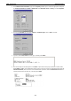
EDS-828 Series EDS Configurator GUI Search by IP address This utility is used to search for one EDS switch at a time. Note that the search is conducted by IP address, so you should be able to locate any EDS switch that is properly connected to your LAN, WAN, or even the Internet. Start by clicking on the Specify by IP address icon Server menu. , or by selecting Specify IP address under the List The Search Server with IP Address window will open.
EDS-828 Series EDS Configurator GUI Modify IP Address You may use the Modify IP Address function to reconfigure the EDS’s network settings. Start by clicking on the Modify IP address icon , or by selecting Modify IP address under the Configuration menu. The Setup Configuration window will open. Checkmark the box to the left of those items that you wish to modify, and then Disable or Enable DHCP, and enter IP Address, Subnet mask, Gateway, and DNS IP. Click OK to accept the changes to the configuration.
EDS-828 Series EDS Configurator GUI 3. You may use a standard text editor, such as Notepad under Windows, to view and modify the newly created configuration file. Import Configuration The Import Configuration function is used to import an entire configuration from a text file to an EDS switch.
EDS-828 Series EDS Configurator GUI 3. The Setup Configuration window will be displayed, with a special note attached at the bottom. Parameters that have been changed will be activated with a checkmark. You may make more changes if necessary, and then click on OK to accept the changes. 4. Click on Yes in response to the following warning message to accept the new settings.
EDS-828 Series EDS Configurator GUI 1. Enter the switch’s User Name and Password when prompted, and then click OK. 2. When the Unlock status window reports Progress as OK, click on the Close button in the upper right corner of the window. 3. The status of the switch will now read Unlocked.
A A. MIB Groups The EDS-828 comes with built-in SNMP (Simple Network Management Protocol) agent software that supports cold/warm start trap, line up/down trap, and RFC 1213 MIB-II. The standard MIB groups that the EDS-828 series support are: MIB II.1—System Group sysORTable MIB II.2—Interfaces Group ifTable MIB II.4—IP Group ipAddrTable ipNetToMediaTable IpGroup IpBasicStatsGroup IpStatsGroup MIB II.5—ICMP Group IcmpGroup IcmpInputStatus IcmpOutputStats MIB II.
EDS-828 Series MIB Groups MIB II.
B B. Modbus/TCP Map EDS-828 Modbus information v1.
EDS-828 Series 0x0055 Modbus/TCP Map 3 words Ethernet MAC Address Ex: MAC = 00-01-02-03-04-05 Word 0 Hi byte = 0x00 Word 0 Lo byte = 0x01 Word 1 Hi byte = 0x02 Word 1 Lo byte = 0x03 Word 2 Hi byte = 0x04 Word 2 Lo byte = 0x05 0x0058 1 word Power 1 0x0000:Off 0x0001:On 0x0059 1 word Power 2 0x0000:Off 0x0001:On 0x005A 1 word Fault LED Status 0x0000:No 0x0001:Yes 0x0080 1 word DI1 0x0000:Off 0x0001:On 0x0081 1 word DI2 0x0000:Off 0x0001:On 0x0082 1 word DO1 0x0000:Off 0x0001:On 0x0083 1
EDS-828 Series 0x1400 to 0x1413(Port 1) Modbus/TCP Map 20 words Port 1 to 10 Description 0x1414 to 0x1427(Port 2) Port Description = "100TX,RJ45." Word 0 Hi byte = ‘1’ Word 0 Lo byte = ‘0’ Word 1 Hi byte = ‘0’ Word 1 Lo byte = ‘T’ … Word 4 Hi byte = ‘4’ Word 4 Lo byte = ‘5’ Word 5 Hi byte = ‘.
EDS-828 Series 0x3301 Modbus/TCP Map 1 word TR 1st Port status 0x0000:Port Disabled 0x0001:Not Redundant 0x0002:Link Down 0x0003:Blocked 0x0004:Learning 0x0005:Forwarding 0x3302 1 word TR 2nd Port status 0x0000:Port Disabled 0x0001:Not Redundant 0x0002:Link Down 0x0003:Blocked 0x0004:Learning 0x0005:Forwarding 0x3303 1 word TR Coupling 0x0000:Off 0x0001:On 0xFFFF:Turbo Ring Not Enable 0x3304 1 word TR Coupling Port status 0x0000:Port Disabled 0x0001:Not Coupling Port 0x0002:Link Down 0x0003:Block
EDS-828 Series 0x3502 Modbus/TCP Map 1 word TR2 Coupling Port Backup status (Only using in Dual Homing) 0x0000:Port Disabled 0x0001:Not Coupling Port 0x0002:Link Down 0x0003:Blocked 0x0004:Learning 0x0005:Forwarding 0xFFFF:Turbo Ring V2 Not Enable 0x3600 1 word TR2 Ring 1 status 0x0000:Healthy 0x0001:Break 0xFFFF:Turbo Ring V2 Not Enable 0x3601 1 word TR2 Ring 1 Master/Slave 0x0000:Slave 0x0001:Master 0xFFFF:Turbo Ring V2 Ring 1 Not Enable 0x3602 1 word TR2 Ring 1 1st Port status 0x0000:Port Disa
EDS-828 Series 0x3683 Modbus/TCP Map 1 word TR2 Ring 2 2nd Port status 0x0000:Port Disabled 0x0001:Not Redundant 0x0002:Link Down 0x0003:Blocked 0x0004:Learning 0x0005:Forwarding 0xFFFF:Turbo Ring V2 Ring 2 Not Enable 0x3700 1 word Turbo Chain Switch Role 0x0000:Head 0x0001:Member 0x0002:Tail 0xFFFF: Turbo Chain Not Enable 0x3701 1 word Turbo Chain 1st Port status 0x0000: Link Down 0x0001: Blocking 0x0002: Blocked 0x0003: Forwarding 0xFFFF:Turbo Ring V2 Ring 2 Not Enable 0x3702 1 word Turbo Chain