EDS-G500E Series Hardware Installation Guide Moxa EtherDevice™ Switch First Edition, July 2013 2013 Moxa Inc. All rights reserved.
Package Checklist The EDS-G500E is shipped with the following items. If any of these items are missing or damaged, please contact your customer service representative for assistance.
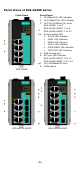
Panel Views of EDS-G500E Series Front Panel Front Panel 1. 1000BaseT(X) LED indicator 2. 10/100BaseT(X) LED indicator 3. 10/100/1000BaseT(X) ports EDS-G508E: 1 to 8 EDS-G512E-4GSFP: 1 to 8 EDS-G516E-4GSFP: 1 to 12 4. System status LED: • STATE LED indicator • PWR1 LED indicator • PWR2 LED indicator • FAULT LED indicator • MSTR/HEAD LED indicator • CPLR/TAIL LED indicator 5. USB storage port 6. SFP port LED indicator EDS-G512E-4GSFP: 9 to 12 EDS-G516E-4GSFP: 13 to 16 7. 100/1000BaseSFP slots 8.
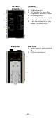
Top Panel Top Panel 1. Reset button 2. USB console port 3. DIP switches for Turbo Ring, Ring Master, and Ring Coupler 4. Grounding screw 5. 4-pin terminal block for digital input and power input 2 6. 4-pin terminal block for relay output and power input 1 Rear Panel Rear Panel 1. Screw holes for wall mounting kit 2.
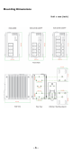
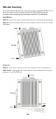
Mounting Dimensions Unit = mm (inch) -5-
DIN-Rail Mounting The metal DIN-rail kit is fixed to the back panel of the EDS-G500E series when you take it out of the box. Mount the EDS-G500E series on corrosion-free mounting rails that meet the EN 60715 standard. Installation STEP 1—Insert the upper lip of the DIN rail into the DIN-rail mounting kit. STEP 2—Press the EDS-G500E series towards the DIN rail until it snaps into place. Removal STEP 1—Pull down the latch on the mounting kit with a screwdriver.
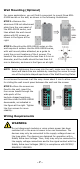
Wall Mounting (Optional) For some applications, you will find it convenient to mount Moxa EDSG500E series on the wall, as shown in the following illustrations: STEP 1—Remove the aluminum DIN rail attachment plate from the rear panel of the EDS-G500E series, and then attach the wall mount plates with M3 screws, as shown in the figure at the right. STEP 2—Mounting the EDS-G500E series on the wall requires 4 screws.
ATTENTION This unit is a built-in type. When the unit is installed in another piece of equipment, the equipment enclosing the unit must comply with fire enclosure regulation IEC 60950/EN60950 (or similar regulation). ATTENTION Safety First! Be sure to disconnect the power cord before installing and/or wiring your Moxa EtherDevice Switch. Calculate the maximum possible current in each power wire and common wire. Observe all electrical codes dictating the maximum current allowable for each wire size.
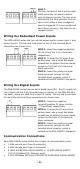
FAULT: The two contacts of the 6-pin terminal block connector are used to detect user-configured events. The two wires attached to the fault contacts form an open circuit when a user-configured event is triggered. If a user-configured event does not occur, the fault circuit remains closed. Wiring the Redundant Power Inputs The EDS-G500E series has two sets of power inputs—power input 1 and power input 2. The top and front views of one of the terminal block connectors are shown here.
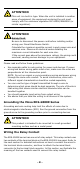
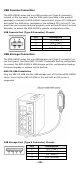
USB Console Connection The EDS-G500E series has one USB console port (type B connector), located on the top panel. Use the USB cable (provided in the product package) to connect the EDS-G500E's console port to your PC's USB port and install the USB driver (available in the software CD) on the PC. You may then use a console terminal program, such as Moxa PComm Terminal Emulator, to access the EDS-G500E’s console configuration utility.
1000BaseT Ethernet Port Connection 1000BaseT data is transmitted on differential TRD+/- signal pairs over copper wires. MDI/MDI-X Port Pinouts Pin 1 2 3 4 5 6 7 8 Signal TRD(0)+ TRD(0)TRD(1)+ TRD(2)+ TRD(2)TRD(1)TRD(3)+ TRD(3)- 100/1000BaseSFP (mini-GBIC) Fiber Port The Gigabit Ethernet ports on the EDS-G500E series are 100/1000BaseSFP Fiber ports, which require using the 100M or 1G mini-GBIC fiber transceivers to work properly.
paper clip or toothpick, to depress the Reset button. This will cause the STATE LED to blink once a second. After depressing the button for 5 continuous seconds, the STATE LED will start to blink rapidly. This indicates that factory default settings have been loaded and you can release the reset button. When the ABC-02-USB is connected to the EDS-G500E Ethernet switch, the reset button allows quick configuration and backs up log files to the ABC-02-USB.
“Turbo Ring V2” DIP Switch Settings DIP 1 DIP 2 DIP 3 ON: Enables the ON: Enables this ON: Enables the default “Ring EDS as the Ring default “Ring Coupling Master. Coupling” port. (backup)” port when DIP switch 3 is already enabled. OFF: Enables the OFF: This EDS OFF: Do not use default “Ring will not be the this EDS as a ring Coupling Ring Master. coupler. (primary)” port when DIP switch 3 is already enabled. DIP 4 ON: Activates DIP switch 1, 2, and 3 to configure “Turbo Ring V2” settings.
LED Color Status On PWR1 Amber Off On PWR2 Amber Off On MSTR/ Green HEAD Blinking Off On CPLR/ Green TAIL Blinking Off Description 5. Invalid Ring port connection. Power is being supplied to the main module’s power input PWR1. Power is not being supplied to the main module’s power input PWR1. Power is being supplied to the main module’s power input PWR2. Power is not being supplied to the main module’s power input PWR2. 1.
LED Color 100M Amber (SFP) 1000M Green (SFP) Status On Blinking Off On Blinking Off Description SFP port’s 100 Mbps link is active. Data is being transmitted at 100 Mbps. SFP port’s 100 Mbps link is inactive. SFP port’s 1000 Mbps link is active. Data is being transmitted at 1000 Mbps. SFP port’s 1000 Mbps link is inactive.
Dimension 79.2 x 135 x 137 mm (3.1 x 5.3 x 5.4 in) Installation DIN-rail mounting, wall mounting (with optional kit) Environmental Limits Operating -10 to 60°C (14 to 140°F) for standard models Temperature -40 to 75°C (-40 to 167°F) for -T models Storage -40 to 85°C (-40 to 185°F) Temperature Ambient Relative 5 to 95% (non-condensing) Humidity Altitude Up to 2000m Note: Please contact Moxa if you require products guaranteed to function properly at higher altitude.