Industrial Protocols User’s Guide Sixth Edition, April 2014 www.moxa.com/product © 2014 Moxa Inc. All rights reserved. Reproduction without permission is prohibited.
Industrial Protocols User’s Guide The software described in this manual is furnished under a license agreement and may be used only in accordance with the terms of that agreement. Copyright Notice ©2014 Moxa Inc., All rights reserved. Trademarks The MOXA logo is a registered trademark of Moxa Inc. All other trademarks or registered marks in this manual belong to their respective manufacturers.
Table of Contents 1. MODBUS/TCP MAP ............................................................................................................................ 1-1 Introduction ....................................................................................................................................... 1-1 Data Format and Function Code ............................................................................................................ 1-1 Configuring MODBUS/TCP on Moxa Switches ..........
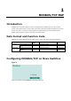
1 1. MODBUS/TCP MAP Introduction MODBUS TCP is a protocol commonly used for the integration of a SCADA system. It is also a vendorneutral communication protocol used to monitor and control industrial automation equipment such as PLCs, sensors, and meters. In order to be fully integrated into industrial systems, Moxa’s switches support Modbus TCP/IP protocol for real-time monitoring in a SCADA system. Data Format and Function Code MODBUS TCP supports different types of data format for reading.
Industrial Protocols MODBUS/TCP MAP Type 2: New UI 2.0 Modbus TCP is enabled by default. To disable Modbus TCP, uncheck Enable Modbus TCP then click Apply. MODBUS Data Map and Information Interpretation of Moxa Switches The data map addresses of Moxa switches shown in the following table start from MODBUS address 30001 for Function Code 4. For example, the address offset 0x0000 (hex) equals MODBUS address 30001, and the address offset 0x0010 (hex) equals MODBUS address 30017.
Industrial Protocols MODBUS/TCP MAP 0x0058 1 word HEX 0x0059 1 word HEX 0x005A 1 word HEX 0x0080 1 word HEX 0x0081 1 word HEX 0x0082 1 word HEX 0x0083 1 word HEX Port Information 0x1000 to 1 word 0x1011 HEX 0x1100 to 0x1111 1 word HEX 0x1200 to 0x1211 1 word HEX 0x1300 to 0x1311 1 word HEX 0x1400 to 0x1413 (Port 1) 20 words ASCII Word 0 Hi byte = 0 x 00 Word 0 Lo byte = 0 x 01 Word 1 Hi byte = 0 x 02 Word 1 Lo byte = 0 x 03 Word 2 Hi byte = 0 x 04 Word 2 Lo byte = 0 x 05
Industrial Protocols 0x2300 to 0x2323 MODBUS/TCP MAP 2 words HEX Redundancy Information 0x3000 1 word HEX 0x3100 1 word HEX 0x3200 to 0x3211 1 word HEX 0x3300 1 word HEX 0x3301 1 word HEX 0x3302 1 word HEX 0x3303 1 word HEX 0x3304 1 word HEX 0x3305 1 word HEX 0x3500 1 word HEX Received MODBUS response: 0x44332211 Word 0 = 4433 Word 1 = 2211 port 1 to 8 Rx Error Packets Ex: port 1 Rx Error Packet Amount = 44332211 Received MODBUS response: 0x44332211 Word 0 = 4433 Word 1 = 2
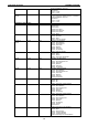
Industrial Protocols MODBUS/TCP MAP 0x3501 1 word HEX TurboRing V2 Coupling Port Primary Status (Used in Dual Homing, Coupling Backup, and Coupling Primary) 0x0000:Port Disabled 0x0001: Not Coupling Port 0x0002: Link Down 0x0003: Blocked 0x0004: Learning 0x0005: Forwarding 0xFFFF: Turbo Ring V2 is Not Enabled 0x3502 1 word HEX 0x3600 1 word HEX 0x3601 1 word HEX 0x3602 1 word HEX 0x3603 1 word HEX 0x3680 1 word HEX 0x3681 1 word HEX 0x3682 1 word HEX 0x3683 1 word HEX 0x3700
Industrial Protocols 0x3702 MSTP Register 0x4000 ~ 0x407F MODBUS/TCP MAP 1 word HEX 1 word, 0x0103 => port role = DesignatedPort port state = Forwarding HEX 0x4080 ~ 0x40FF 1 word, 0x0103 HEX => port role = DesignatedPort port state = Forwarding 0x4100 ~ 0x417F 1 word, 0x0103 HEX => port role = DesignatedPort port state = Forwarding 0x4180 ~ 0x41FF 1 word, 0x0103 HEX => port role = DesignatedPort port state = Forwarding 0x4200 ~ 0x427F 1 word, 0x0103 HEX => port role = DesignatedPort = port s
Industrial Protocols 0x4380 ~ 0x43FF MODBUS/TCP MAP 1 word, 0x0103 HEX => port role = DesignatedPort port state = Forwarding MSTP MSTI7 Port Role / Port State 0x00: DisabledPort / 0x00 Port Disabled 0x01: DesignatedPort / 0x01Discarding 0x02: RootPort / 0x02Learning 0x03: AlternatePort / 0x03Forwarding 0x04: BackupPort 0x05: MasterPort 0x06: Not MSTP Port / 0x06Not MSTP Port 0xFFFF: MSTP Not Enable 1-7
2 2. EtherNet/IP Introduction EtherNet/IP is an Industrial Ethernet Protocol defined by the ODVA association. The protocol is open to the public and vendors can implement EtherNet/IP into their industrial devices without incurring a license fee. Many vendors have adopted this protocol as the standard communication protocol between devices. For example, Rockwell Automation uses EtherNet/IP as the standard protocol for their Logix controllers over Ethernet networks.
Industrial Protocols EtherNet/IP Type 2: New UI2.0 The default Modbus TCP support is enabled. To disable the Modebus TCP support, uncheck the Enable Modbus TCP then click Apply to activate the setting. CIP Objects of EtherNet/IP Several communication objects are defined in CIP (Common Industrial Protocol).
Industrial Protocols EtherNet/IP Instance Attribute List Attr ID Name 1 2 3 4 Access Rule Get Get Get Get (Struct.) Data Type 5 6 7 Get Get Get Status Serial Number Product Name 15 Get/Set Assigned Name 17 Get/Set Geographic Location Vendor ID Device Type Product Code Revision UINT (16) UINT (16) UINT (16) (Struct.) USINT (8) USINT (8) WORD (16) UDINT (32) SHORT_ STRING STRINGI Major Minor STRINGI Description 991, the vendor ID of Moxa. 0 x 307, “Managed Ethernet Switch”.
Industrial Protocols EtherNet/IP Product Code Table Product Code Model Name 0x0001 n/a 0x0002 n/a 0x0003 EDS-726 0x0004 n/a 0x0005 EDS-518A 0x0006 EDS-405A 0x0007 EDS-408A 0x0008 EDS-505A 0x0009 EDS-508A 0x000A EDS-510A 0x000B EDS-516A 0x000C EDS-728 0x000D PT-7728 0x000E EDS-828 0x000F PT-7828 0x0010 PT-7710 0x0011 IKS-6726 or PT7728S_old 0x0034 TN-5818 0x0035 IKS-G6824 0x0036 ICS-G7826 0x0037 ICS-G7828 0x0038 ICS-G7748 0x0039 ICS-G7750 0x003A ICS-G7752 0x003B ICS-G7848 0x003C ICS-G7850 0x003D ICS-G7852
Industrial Protocols EtherNet/IP Instance Attribute List Attr ID Access Rule 1 Get Name Status (Struct.) Data Type DWORD (32) 2 Get Configurat ion Capability DWORD (32) 3 Get/Set Configurat ion Control DWORD (32) 4 Get Physical Link Object 5 Get/Set Interface Configurat ion IP Address Path Size Path Network Mask Gateway Address Name Server Name Server2 Domain Name 6 Get/Set Host Name (Struct.) UINT (16) Padded EPATH (Struct.
Industrial Protocols EtherNet/IP The following tables summarize the attributes of the Ethernet Link object. There are some vendor specific attributes in the table (Starting from attribute Id 100).
Industrial Protocols EtherNet/IP Deferred UDINT (32) Transmissi ons Late UDINT (32) Collisions Excessive Collisions UDINT (32) MAC Transmit Errors Carrier Sense Errors UDINT (32) UDINT (32) Frame Too UDINT (32) Long 6 Get/Set Interface Control Interface Label Interface Port Index Interface Port Description Broadcast Storm Protection MAC Receive Errors UDINT (32) Control Bits WORD (16) Forced Interface Speed UINT (16) (Struct.
Industrial Protocols EtherNet/IP 114 Get Tx Multicast Packet UDINT(32) 115 Get Rx Multicast Packet UDINT(32) 116 Get Tx Broadcast Packet UDINT(32) 117 Get Rx Broadcast Packet UDINT(32) 118 Get Redundant Port Status UDINT(32) Total number of TX multicast packets Total number of RX multicast packets Total number of TX broadcast packets Total number of RX broadcast packets Bit 0 = Disable Bit 1 = Not Redundant port Bit 2 = Link down Bit 3 = Blocking Bit 4 = Learning Bit 5 = Forwarding In
Industrial Protocols EtherNet/IP Class Attribute List Attr ID 1 Access Rule Get Name Revision Data Type UINT (16) Description Revision of this object Instance Attribute List Attr ID 3 4 Access Rule Get/Set Get Name Data Size (Struct.) Data Type Array of BYTE UINT (16) Description The implicit messaging content Number of bytes in Attr.
Industrial Protocols EtherNet/IP Connection Manager Object The Connection Manager Class allocates and manages the internal resources associated with both I/O and Explicit Messaging connections. The class code is 0x06. There is one instance of this object. The supported connection trigger type is cyclic and change of state. The instance attribute list is introduced as the following.
Industrial Protocols EtherNet/IP 5 Get Port Type Name 6 Get/Set Port Description 7 Get Node Address 9 Get Port Key the string is 64. SHORT_STR String which names the port type. The ING maximum number of characters in the string is 64. SHORT_STR String which describes the port. The ING maximum number of characters in the string is 64. Padded Node number of this device on port. The EPATH range within this data type is restricted to a Port Segment.
Industrial Protocols 3 Get 4 EtherNet/IP USINT (8) Get Switch Port Number Port Exist 5 Get/Set Port Enable ULINT (64) 6 Get Port Link Status ULINT (64) 7 Get/Set IGMP Snooping Enable USINT (8) 8 9 Get/Set Get/Set Query Interval IGMP Enhanced Mode UDINT (32) USINT (8) 14 Get/Set Relay 1 USINT (8) 15 Get/Set Relay 2 USINT (8) 16 Get/Set Power 1 Relay Warning USINT (8) 17 Get/Set Power 2 Relay Warning USINT (8) 18 Get/Set DI 1 (0ff) Relay Warning USINT (8) 19 Get/Se
Industrial Protocols 27 Get/Set EtherNet/IP Reset Device USINT (8) Bits 1= Turbo Ring Bits 2= Turbo Ring v2 Bits 3= Turbo Chain Bits 4= MSTP Reboot and reset to default 1: Reboot the device 2: Reset to default Common Service List Service Code 0x0E 0x10 Implementation Class Instance Service Name Description Get_Attribute_Single Set_Attribute_Single Used to read an object instance attribute Used to modify an object instance attribute Electronic Data Sheet (EDS) File The EDS (Electronic Data
Industrial Protocols EtherNet/IP 1. Open RSLogix 5000 and create a new controller. Click Type and select the Rockwell PLC model of the PLC connected to the Moxa switch. Input a Name and Description for this new controller. 2. Add an Ethernet Module to the I/O Configuration. In the controller organizer window, select I/O Configuration, right click Ethernet under the PLC Ethernet port of the PLC connected to a Moxa switch, and select New Module.
Industrial Protocols EtherNet/IP 3. Under the Communications group, select Generic Ethernet Module to represent Moxa Ethernet switches 4. Configure the Ethernet module with the correct name, description, IP address and connection parameters and click OK. 5. After finishing configuration, the new Ethernet module representing the Moxa Ethernet switch will appear under the I/O Configuration list in the controller organizer window.
Industrial Protocols EtherNet/IP Import the Add-On Instruction (AOI) 1. In the controller organizer window, right click the Add-On Instructions folder, select Import Add-On Instructions and select the correct AOI file (xxx.L5X) to import. NOTE The AOI file is available from the Moxa website or in the software CD. Please make sure to use the latest switch firmware and AOI for programming. 2.
Industrial Protocols EtherNet/IP Add an instance of the AOI in your application 1. Double click the MainRoutine in the Controller Organizer to start the ladder programming. Add the AOI for the specific Moxa Ethernet switch to create a new rung. Create and configure tags for the AOI 1. Right click on the ? in the field of each tag, select New Tag and input a Name for each new tag.
Industrial Protocols EtherNet/IP 2. Add a Name for all AOI tags. For “Switch_Input” and “Switch_Output”, use the scrollbar to select the tag name For all other tags, manually type the tag names: AOI Tag Reference Tag Name AOI_MOXA_408A_v1_0 aoi_408A_instance Switch_Input MOXA_408A:I.Data Switch_Output MOXA_408A:O.
Industrial Protocols EtherNet/IP Click the Communication tab and set up the communication path to the Moxa Ethernet switch for Get_AllMessage 4.
Industrial Protocols EtherNet/IP Click the Communication tab and set up the communication path to the Moxa Ethernet switch for Set_Message 5.
Industrial Protocols EtherNet/IP Download the configured AOI to the Rockwell PLC 1. Click the Network Icon, select the Rockwell PLC connected to the Moxa switch and click Download to install the AOI configuration to the PLC. 2. After finishing configuration, go to the controller organizer window, right click Controller Tags and select Monitor Tags to check if each tag can display the correct value transferred from the Ethernet device.
Industrial Protocols NOTE EtherNet/IP Only Moxa pre-configured tags will display the correct values. Refer to the CIP Tags section below for detailed information. Sample AOI Project For easier AOI installation, Moxa has also provided a sample AOI project, in which all the parameters are configured with default values. The sample project is a (.ACD) file, which is available for download from the Moxa website or software CD.
Industrial Protocols EtherNet/IP Tags for Ethernet Link Object Name Interface Speed Interface Flags Physical Address InOctets InUcastPackets InNucastPackets InDiscards InErrors OutOctets OutUcastPackets OutNucastPackets OutDiscards OutErrors Alignment Errors FCS Errors Single Collisions Multiple Collisions SQE Test Errors Deferred Transmissions Late Collisions Excessive Collisions MAC Transmit Errors Carrier Sense Errors Frame Too Long MAC Receive Errors Control Bits Forced Interface Speed Interface Label
Industrial Protocols Rate Tx Multicast Packet Rx Multicast Packet Tx Broadcast Packet Rx Broadcast Packet Redundant Port Status EtherNet/IP DINT DINT DINT DINT DINT Total number of TX multicast packets Total number of RX multicast packets Total number of TX multicast packets Total number of RX broadcast packets Bit 0 = Disable, Bit 1 = Not Redundant port, Bit 2 = Link down, Bit 3 = Blocking, Bit 4 = Learning, Bit 5 = Forwarding Tags for Moxa Networking Object Data Type: MOXA_Vendor_Object_v0 Name System
Industrial Protocols EtherNet/IP Reset Device SINT Bit 1: Turbo Ring, Bit 2: Turbo Rong v2, Bit 3: Turbo Chain, Bit 4: MSTP 1: restart the device 2: reset to default Pre-configured Tags in the Moxa AOI The Moxa AOI supports all the CIP tags listed in the tables above. But in the AOI, we only pre-configure logic links between selected tags and Moxa switches. To monitor the non-configured tags, PLC programmers need to create the links manually.
Industrial Protocols ※ ※ ※ ※ ※ ※ ※ ※ ※ ※ Port Object (0xf4) EtherNet/IP Control Bits Forced interface Speed Interface Lable Interface Description Interface Port Description Broadcast Storm Protection Interface Utizatiion Utilization Alarm Upper Threshold Utilization Alarm Lower Threshold Port Link Alarm Port Traffic-Overload Alarm Tx Unicast Packet Rate Rx Unicast Packet Rate Tx Multicast Packet Rate Rx Multicast Packet Rate Tx Broadcast Packet Rate Rx Broadcast Packet Rate Tx Multicast Packet Rx Multic
Industrial Protocols NOTE EtherNet/IP Only Moxa pre-configured tags will display the correct values. Refer to the CIP Tags section above for detailed information. Monitor Tags for Identity Object Click moxa_param Switch_Identity and expand the list to check the values for Identity tags. Monitor Tags for TCPIP Object Click moxa_param Switch_TCPIP and expand the list to check the values for TCPIP tags.
Industrial Protocols EtherNet/IP Monitor Tags for Ethernet Link Object Click moxa_param Switch_Ethernet_Link and expand the list to check the values for per port Ethernet Link tags.
Industrial Protocols EtherNet/IP Monitor Tags for Moxa Networking Object Click moxa_param Switch_Vendor and expand the list to check the values for Moxa custom tags.
Industrial Protocols EtherNet/IP Rockwell FactoryTalk® View Faceplate FactoryTalk® View Faceplate Installation To install the faceplate, you must have Rockwell FactoryTalk® View Studio SE (Site Edition) version 5 or later and a Moxa managed Ethernet switch with firmware version 3.0 or later. Create a FactoryTalk® View Shortcut to the PLC 1. Start the FactoryTalk® View Studio software and select Site Edition (Local). 2. Add a new Site Edition (Local) and enter the Application name.
Industrial Protocols EtherNet/IP 3. Configure a shortcut to the PLC that is running the Moxa AOI. In the Explorer window, right click the newly-added application, select Add New Server and Rockwell Automation Device Server (RSLinx Enterprise), and click OK. 4. The shortcut is named PLC. Click “Yes” to apply the configuration.
Industrial Protocols EtherNet/IP Import FactoryTalk® View Faceplate Graphics 1. Right click Display in the FactoryTalk® View Explorer window, select Import and Export and choose Import graphic information into displays. 2. Select No and Multiple displays batch import file 3. Import all graphics files for FactoryTalk® View faceplate display. NOTE Moxa provides sample graphics files for selected switches, which are available for download at the Moxa website or from the software CD.
Industrial Protocols EtherNet/IP 4. After import, these objects will appear under Displays in the Explorer window. Import FactoryTalk® View Faceplate Local Message 1. Right click Local Message in the FactoryTalk® View Explorer window, select Add Component Into Application and import all the local message files (.loc) NOTE Moxa provides sample local message files for selected switches, which are available for download at the Moxa website or from the software CD..
Industrial Protocols EtherNet/IP 2. After import, these objects will appear under “Local Message” in the Explorer window. Import FactoryTalk® View Faceplate Images 1. Right click Images in the FactoryTalk® View Explorer window, select Add Component Into Application and import all the image files (.bmp) NOTE Moxa provides sample image files for selected switches, which are available for download at the Moxa website or from the software CD.
Industrial Protocols EtherNet/IP 2-35
Industrial Protocols EtherNet/IP Create a New Parameter 1. Right click Parameters in the FactoryTalk® View Explorer window, and select New 2. Create a parameter file that will be associated with the display. Manually input “#1=[PLC]moxa_param”, and “#2=PLC” in the file. In the parameter definition, the shortcut PLC was created earlier.
Industrial Protocols EtherNet/IP Configure FactoryTalk® View Faceplate Display 1. Right click all parameter tabs under Displays in the FactoryTalk® View Explorer window, and select Display Setting. 2. Configure Display Type and Size as shown. For the Moxa custom faceplate, you need to configure three parameters: MOXA_Device Info; MOXA_Port_Setting; MOXA_Port_Status.
Industrial Protocols EtherNet/IP Sample FactoryTalk® View Faceplate Project For easier FactoryTalk® View Faceplate installation, Moxa also provides a sample project, in which all the parameters are configured with default values. The sample project is a (.APA) file, which is available for download from the Moxa website or software CD. You may import the sample project in FactoryTalk® View Faceplate Site Edition (SE). Setting Up a FactoryTalk® View SE Client 1. Launch FactoryTalk® SE client 2.
Industrial Protocols EtherNet/IP 3. Select the application type Local 4. Enter the name of the application and select the language 5.
Industrial Protocols EtherNet/IP 6. Configure the FactoryTalk® View SE Window Properties and input Title bar text with the text you would like to appear in the title bar. 7. Finish the setup and save the configuration Introduction to the Moxa Custom Faceplate The Moxa custom Faceplate consists of three main displays: Device Information, Port Status, and Port Setting. Click the tabs at the top of the screen to change between different displays.
Industrial Protocols EtherNet/IP Device Information The device information display shows general switch information and power and link status. The following table describes fields and values. Field IP Address Netmask MAC Address Serial No. Firmware Ver. CPU Loading (%) Redundant Protocol Power Input 1 Power Input 2 Model name Switch name Field Link Status Power Status Values 192.168.192.253 (factory default) 255.255.255.0 00:90:E8:xx:xx:xx Max. 5 characters V3.
Industrial Protocols EtherNet/IP Port Status The port status display shows information for a selected switch port. Use the right/left buttons to select a switch port.
Industrial Protocols EtherNet/IP Port Setting The Port Setting allows some switch port settings to be changed. Use the right/left buttons to select a switch port and click the Activate button to save the change.
3 3. PROFINET I/O Introduction This section is supported only with EDS-400A-PN, EDS-510E, and EDS-G500E series devices. PROFINET is a communication standard for automation of PROFIBUS & PROFINET International (PI). It is 100% Ethernet-compatible as defined in IEEE standards. With PROFINET, applications can be implemented for production and process automation, safety applications, and the entire range of drive technology.
Industrial Protocols PROFINET I/O I/O Supervisor This can be a programming device, personal computer (PC), or human machine interface (HMI) device for commissioning or diagnostic purposes. I/O Device An I/O device is a distributed I/O field device that is connected to one or more I/O controllers via PROFINET I/O. The I/O device is the provider of input data and the consumer of output data. PROFINET I/O Devices The MOXA switch is a PROFINET I/O device.
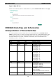
Industrial Protocols PROFINET I/O Configuring PROFINET I/O on Moxa Switches Enable PROFINET I/O Enable PROFINET in WEB UI Type 1 Select the Enable option and click Activate to enable PROFINET I/O. With PROFINET I/O enabled, PROFINET type LLDP will be enabled automatically. Select the Disable option and click Activate to disable PROFINET I/O, the switch will disable PROFINET type LLDP and use standard LLDP. PROFINET special model is enabled by default on the EDS-400A-PN series switches. Type 2: New UI 2.
Industrial Protocols PROFINET I/O Addressing of I/O Data in PROFINET I/O Based on Slot and Sub-Slots The concept of the MOXA PROFINET switch with GSD version 2 is shown the table below. In this structure, each switch port represents one sub-slot. Manufacturer Information Each PROFINET device is addressed based on a MAC address. This address is unique worldwide. The company code (bits 47 to 24) can be obtained from the IEEE Standards Department free of charge.
Industrial Protocols PROFINET I/O PROFINET Cyclic I/O Data The MOXA PROFINET switch provides PROFINET I/O cyclic data and includes the following items: NOTE: The default transfer frequency of PROFINET Cyclic I/O data is 128 ms. There are 3 options available in SIMATIC STEP 7: 128/256/512 ms. PROFINET Cyclic I/O Data Table Category Direction Byte Bit Device Port Input Input 0 1 Name Description 0 Device status 0 is failed status, 1 is OK.
Industrial Protocols PROFINET I/O PROFINET I/O Parameters MOXA defines comprehensive PROFINET I/O parameters for more flexible settings and monitoring. There attributes are readable or writable. PROFINET I/O parameters use PROFINET acyclic data to achieve communication in the network. You can use the SIMATIC STEP 7 tool or engineering deployment software to edit it. There are 3 categories of parameters, including Device Parameters, Device Status and Port Parameters.
Industrial Protocols 4 5 6 7 8 9 10 11 12 13 DI 1 Status DI 2 Status Redundant Mode Ring Status Redundant Port 1 Status Redundant Port 2 Status Ring Coupling Mode Coupling Port 1 Status Coupling Port 2 Status Connection PROFINET I/O ro ro ro ro ro ro ro ro ro ro 1 OK 2 Power 2 fails 0 Unavailable 1 Closed 2 Open 0 Unavailable 1 Closed 2 Open 0 Unavailable 1 RSTP 2 Turbo Ring V1 3 Turbo Ring V2 4 Turbo Chain 0 Unavailable 1 Healthy 2 Break 0 Un
Industrial Protocols 2 3 4 5 6 7 Port Link State Port Speed Port duplex Port Auto-negotiation Port flow control Port MDI/MDIX PROFINET I/O ro ro ro ro ro ro 2 On 0 Unavailable 1 Link is up 2 Link is down 0 Unavailable 1 10 2 100 3 1000 0 Unavailable 1 Half 2 Full 0 Unavailable 1 Off 2 On 0 Unavailable 1 Off 2 On 0 Unavailable 1 MDI 2 MDIX Step 7 Integration Overview of Operation Procedure The following steps show how to integrate the switch into a
Industrial Protocols PROFINET I/O Create a PROFINET I/O Subnet Project In SIMATIC Manager menu bar, click File > New Project Name your project in the Name field then click OK. Insert a station in your project Right click in category column > Insert New Object > your PLC series (here we select SIMATIC 300 station). Then you can see the new object in the project. Double click on the Hardware.
Industrial Protocols PROFINET I/O Add Rack in HW Config After double-clicking on HW, you will see the HW Config window. Drag a rack from the side bar to main dashboard. In here, we drag Rail, which is under the Rack-300 folder, to the main screen. Search PRODINET Ethernet devices Use Edit Ethernet Node to browse device information in PROFINET networks.
Industrial Protocols PROFINET I/O Edit Ethernet Node Then click Browse Click Start to search devices. Use STEP 7 through PROFINET DCP to discover devices in networks. Find PLC/switch IP addresses, MAC addresses, and device names here. Add PLC CPU in HW Config Select your PLC CPU and drag it to the rack slot 2. Please select by PLC you used. Here we will select 6ES7315-2EH14-0AB0 V3.1.
Industrial Protocols PROFINET I/O Then click Properties, the Ethernet interface dialog will pop out. Fill in your PLC IP address in “IP address” column. Then click New in subnet to create a new Ethernet subnet. Here we will create a subnet named “PROFINET Ethernet” PROFINET I/O Ethernet subnet project accomplished GSD File Installation 1. Open SIMATIC manager on your PC. 2. Open your project.
Industrial Protocols 3. Open hardware configuration. 4. Install the GSD file: PROFINET I/O Put the GSD file and icon file on your PC at the same folder Select “Install GSD File” and install the GSD file just saved. 5. You will find the new MOXA switch under PROFINET IO > Additional Field Devices > Network Components > 6. Use Drag & Drop to pull the MOXA switch onto the bus cable. And you can see the MOXA switch icon MOXA EtherDevice Switch. displayed on the screen • Product Icons Ex.
Industrial Protocols PROFINET I/O Device Configuration 1. Browse the switch Select PLC > Ethernet > Edit Ethernet Node to open the Browse dialog. After the Edit Ethernet Node dialog box appears, click Browse Select your target switch and click OK 2. Assign IP address and Device name a. Give the switch an IP address and subnet mask Click Assign IP configuration b.
Industrial Protocols PROFINET I/O c. Click Close to finish NOTE 3. The field Device name does not allow any empty spaces in the name. If the device name is entered with a space, the system will remove words after the space automatically. Set IP address and device for your project a. b. Double-click the switch icon to open switch property menu. Set the Device name and IP address corresponding with those you have just assigned in STEP 7.
Industrial Protocols c. 4. 5. PROFINET I/O Click Save and Compile then click download to Module. Configuring device properties a. Select the switch and double-click the first sub-module slot 0 to set device properties. b. Select Parameters and change the device parameter settings. c. Click Save and Compile, then click download to Module Configuring I/O cycle a. b. Select the switch and double-click the sub-module X1 to set the I/O cycle. Select IO Cycle and change the I/O cycle settings.
Industrial Protocols 6. 7. PROFINET I/O Configuring port property a. Select the switch and double-click the sub-module X1 PN to set port property. b. Select Parameters. c. Change the port parameters settings. d. Click Save and Compile then click download to Module. Configuring connection options a. Select the switch and double-click the sub-module X1 PN to set port options. b. Select Options. c. Change the port option settings. d.
Industrial Protocols PROFINET I/O Save and Load the Project into the PLC Click the icon (in red box) to download project configuration to the PLC. After the project is configured, SIMATIC STEP 7 will load all information required for data exchange to the I/O Controller (PLC), including the IP addresses of the connected I/O devices. Monitoring the Switch Monitor PROFINET I/O Cyclic Data MOXA switches provide PROFINET I/O cyclic data for real-time monitoring.
Industrial Protocols PROFINET I/O example, address 0.1 is Bit 1 in the PROFINET Cyclic I/O data table. It represents Power 1 status of the switch. 1 means Power 1 exists and Green will be displayed in the Modify/monitor window NOTE: Refer to the PROFINET Cyclic I/O data table in chapter 5.1 for the meanings of each address. To monitor Port data, follow the same steps, drag Port data in the side bar and drop it onto slot 2. MOXA PROFINET I/O cyclic data in the slot 1 and 2 Then right click.
Industrial Protocols PROFINET I/O Module Information MOXA switch supports SIMATIC STEP 7 Ethernet traffic information monitoring and PROFINET alarms. These attributes can be monitored in module information dialog. Following are the steps of operation. Select MOXA switch icon on the screen. Then, click menu bar PLC > Module Information The module information dialog will then pop up. Port Statistics Output Select Statics tags. Find out each port traffic information list below.
Industrial Protocols PROFINET I/O Statistics tab lists each port traffic status and the number of packets. Click Update to refresh the data. I/O Device Diagnostics Moxa PROFINET switches support PROFINET alarms. These alarm messages will be sent by the switch immediately when an event is triggered. These alarms can be enabled/disabled using PROFINET I/O parameters(see chapter PROFINET I/O Parameters ). Select IO Device Diagnostics tab to view alarms received by the PLC.
Industrial Protocols PROFINET I/O Topology Editor MOXA devices support SIMATIC STEP 7 Topology editor. Click Topology Editor. View each port’s connection status in table view tag. In the Offline/Online Comparison tab, you can compare device partner ports. Click Start to discover connection relationships.
Industrial Protocols PROFINET I/O You can also draw the connection of each port manually in Graphic view tab.