MOXA EtherDevice Switch EDS-308/305 Hardware Installation Guide Sixth Edition, March 2005 Moxa Networking Co., Ltd. Tel: +886-2-2910-1230 Fax: +886-2-2910-1231 www.moxa.com support@moxanet.com support@moxa.
Overview MOXA EtherDevice™ EDS-308/305 Series, which consists of 8- and 5- port smart Ethernet switches, provides an economical solution for your Ethernet connections. As an added bonus, the built-in smart alarm function helps system maintainers monitor the health of your Ethernet network. EDS-308/305 have a wide operating temperature range of -40 to 75°C, and are designed to withstand a high degree of vibration and shock.
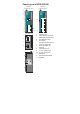
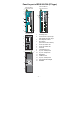
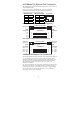
Panel Layout of EDS-305/308 EDS-305 Front Panel View EDS-308 Front Panel View 2 5 6 7 8 8 9 10 11 11 Top Panel View 1. 2. 1 V2+ 5. 6. 7. 8. 9. Grounding screw Terminal block for power input PWR1/PWR2 and relay output Heat dissipation orifices DIP switches (EDS-308 has 8 DIP switches) Power input PWR1 LED Power input PWR2 LED Fault LED 10/100BaseT(X) Port TP port’s 100 Mbps LED 10. 11. 12. 13.
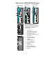
Panel Layout of EDS-305/308 (SC-type) EDS-308-M-SC Front Panel View EDS-305-M-SC Front Panel View EDS-308-MM-SC Front Panel View 2 5 6 7 5 6 7 12 12 13 8 12 13 13 9 10 11 Top Panel View NOTE: The appearance of EDS-305-S-SC is identical to EDS-305-M-SC, the appearance of EDS-308-S-SC is identical to EDS-308-M-SC, and the appearance of EDS-308-SS-SC is identical to EDS-308-MM-SC. 1 V2+ PWR2 V2- 2 FAULT V1+ PWR1 V1V1 V2 INPUTS: 24 VDC 3 1. 2. PORT ALARM 1 2 ON 3 5 14 15 14 10. 11.
Panel Layout of EDS-305/308 (ST-type) EDS-308-MM-ST Front Panel View EDS-305-M-ST Front Panel View 2 5 6 7 5 6 7 12 13 12 13 8 9 10 11 Top Panel View 1. 2. 1 V2+ 5. 6. 7. 8. 9. Grounding screw Terminal block for power input PWR1/PWR2 and relay output Heat dissipation orifices DIP switches (EDS-308 has 8 DIP switches) Power input PWR1 LED Power input PWR2 LED Fault LED 10/100BaseT(X) Port TP port’s 100 Mbps LED 10. 11. 12. 13. 14. 15.
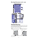
Mounting Dimensions (unit = mm) 21.00 30.00 54.00 9.50 Side View 135.00 (unit = mm) 105.00 25.71 15.10 13.10 25.40 + + + 39.37 + 13.90 18.20 13.90 9.75 + 6 + 26 + 10 + 10 + 5 30.50 7.75 7.75 13 18 13 3.50 + + 6.00 3.50 + + 6.00 + 23.15 46.77 135.00 Front View + + + + + + + + Rear View + + Panel Mount Kit DIN-Rail Mounting The aluminum DIN-Rail attachment plate should already be fixed to the back panel of EDS-308/305 when you take it out of the box.
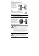
Wall Mounting (optional) For some applications, you will find it convenient to mount EDS-308/305 on the wall, as illustrated below. STEP 1: Remove the aluminum DIN-Rail attachment plate from EDS-308/305’s rear panel, and then attach the wall mount plates, as shown in the diagram below. top plate ⇒ bottom plate STEP 2: Mounting EDS-308/305 on the wall requires 4 screws. Use the switch, with wall mount plates attached, as a guide to mark the correct locations of the 4 screws.
WARNING This equipment has been evaluated as EEx nC IIC T4 equipment under DEMKO Certificate No. 03 ATEX 0324537U. Each module is marked II 3G and is suitable for use in Zone 2 Explosive Atmospheres. The device must be installed in a minimum IP 54 enclosure as defined in IEC 60529 and EN 60529. WARNING This unit is a built-in type. When the unit is installed in another piece of equipment, the equipment enclosing the unit must comply with fire enclosure regulation IEC 60950/EN60950 (or similar regulation).
Wiring the Alarm Contact The Alarm Contact consists of the two middle contacts of the terminal block on EDS’s top panel. You may refer to the next section for detailed instructions on how to connect the wires to the terminal block connector, and how to attach the terminal block connector to the terminal block receptor. In this section, we explain the meaning of the two contacts used to connect the Alarm Contact.
/100BaseT(X) Ethernet Port Connection The 10/100BaseT(X) ports located on EDS’s front panel are used to connect to Ethernet-enabled devices. Below we show pinouts for both MDI (NIC-type) ports and MDI-X (HUB/Switch-type) ports, and also show cable wiring diagrams for straight-through and cross-over Ethernet cables.
SC-Port Pinouts SC-Port to SC-Port Cable Wiring A A B B Tx Cable Wiring Rx A B ST-Port Pinouts A B ST-Port to ST-Port Cable Wiring A A B B Tx Cable Wiring Rx A B A B ATTENTION This is a Class 1 Laser/LED product. To avoid causing serious damage to your eyes, do not stare directly into the Laser Beam. Redundant Power Inputs Both power inputs can be connected simultaneously to live DC power sources.
DIP Switch Settings EDS-308 Series DIP Switches ON 1 2 EDS-305 Series DIP Switches DIP 3 4 5 6 7 ON 1 8 2 DIP 3 4 5 ON: Enables the corresponding PORT Alarm. If the port’s link fails, the relay will form an open circuit and the fault LED will light up. Off: Disables the corresponding PORT Alarm. The relay will form a closed circuit and the Fault LED will never light up. LED Indicators The front panel of MOXA EtherDevice Switch contains several LED indicators.
Auto MDI/MDI-X Connection The Auto MDI/MDI-X function allows users to connect EDS-308/305’s 10/100BaseTX ports to any kind of Ethernet device, without needing to pay attention to the type of Ethernet cable being used for the connection. This means that you can use either a straight-through cable or cross-over cable to connect EDS-308/305 to Ethernet devices. Fiber Ports MOXA EDS-308/305’s fiber switched ports operate at a fixed 100 Mbps speed and full-duplex mode to provide the best performance.
network (such as the occasional multi-cast packet) are forwarded to all ports. EDS-308/305 operates in the store-and-forward switching mode, which eliminates bad packets and enables peak performance to be achieved when there is heavy traffic on the network. Switching and Address Learning MOXA EDS-308/305 has an address table that can hold up to 1K node addresses, which makes it suitable for use with large networks.
Optical Fiber Distance, km Wavelength, nm Min. TX Output, dBm Max. TX Output, dBm Sensitivity, dBm Recommended Diameter (Core/Cladding) µm Multi mode 5 1300 -20 -14 -34 to -30 Single mode, 15 15 1310 -15 -6 -36 to -32 Single mode, 40 40 1310 -5 0 -36 to -32 Single mode, 80 80 1550 -5 0 -36 to -32 50/125 (1 dB/km, 800 MHz × km) 9/125 9/125 9/125 Power Input Voltage 12 to 48 VDC, redundant inputs Input Current @ 24VDC 0.25 A (EDS-305, EDS-305-M, EDS-305-S, EDS-308) 0.
MOXA Internet Services Customer satisfaction is our number one concern, and to ensure that customers receive the full benefit of our products, Moxa has set up on-line support services to provide technical support, driver updates, product information, and user’s manual updates. E-mail for technical support: support@moxanet.com support@moxa.com Website for up to date product information: www.moxa.