MOXA EtherDevice™ Switch EDS-510A Series Hardware Installation Guide First Edition, September 2006 Moxa Networking Co., Ltd. Tel: +886-2-2910-1230 Fax: +886-2-2910-1231 www.moxa.com support@moxanet.com (Worldwide) support@usa.moxa.
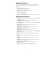
Package Checklist The EDS-510A is shipped with the following items. If any of these items are missing or damaged, please contact your customer service representative for assistance.
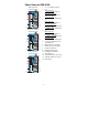
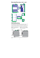
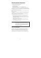
Panel Views of EDS-510A 1. 2. EDS-510A-3GT Front Panel View 6 7 8 9 10 1 5 4 3 2 1 11 12 14 13 EDS-510A-1GT2SFP Front Panel View 4. 6 7 8 9 10 1 5 4 3 2 11 12 1 13 14 3. 5.
Top Panel: Top Panel View 1. Ground screw 2. RS-232 console port 5 3. 4. 6 5. Heat dissipation orifices DIP switches for Ring Master, Ring Coupler, and Turbo Ring 6-pin terminal block for DI 1, DI 2, and PWR 2 6-pin terminal block for PWR1, Relay 1, and Relay 2 1 RS-232 CONSOLE V2PWR2 V2+ 2 DI1 I1 DI2 I2 3 RELAY1 1 2 3 4 4 OFF ------ RELAY2 MASTER COUPLER TURBO RING ON V1+ PWR1 V1- 6. Rear Panel View 2 7 1 Rear Panel: 7. Screw holes for Wall Mounting Kit 8.
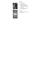
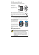
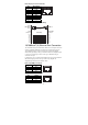
Mounting Dimensions (unit = mm) 15.0 30.00 51.3 9.00 13.9 135.00 135.00 35.00 DlN-Rail DlN-Rail Kit Front View 105.00 Side View 3.5 6 57.05 66.80 24.3 6 55 7.5 46.77 7.5 27.20 48.30 39.37 10 10 5 7.75 24.56 DlN-Rail Kit 13.9 30.50 18.2 7.75 13.9 80.2 Rear View Wall Mounting Kit DIN-Rail Mounting The aluminum DIN-Rail attachment plate should already be fixed to the back panel of the EDS-510A when you take it out of the box.
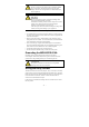
Wall Mounting (Optional) For some applications, you will find it convenient to mount MOXA EDS-510A on the wall, as shown in the following illustrations: STEP 1—Remove the aluminum DIN-Rail attachment plate from the rear panel of the EDS-510A, and then attach the wall mount plates, as shown in the figure at the right. Ö STEP 2—Mounting the EDS-510A on the wall requires 4 6.0 mm screws. Use the EDS-510A, with wall mount plates attached, as a guide to mark the correct locations of the 4 screws.
ATTENTION This unit is a built-in type. When the unit is installed in another piece of equipment, the equipment enclosing the unit must comply with fire enclosure regulation IEC 60950/EN60950 (or similar regulation). ATTENTION Safety First! Be sure to disconnect the power cord before installing and/or wiring your MOXA EtherDevice Switch. Calculate the maximum possible current in each power wire and common wire. Observe all electrical codes dictating the maximum current allowable for each wire size.
RELAY1 RELAY2 RELAY1 RELAY2 FAULT: The two sets of relay contacts of the 6-pin terminal block connector are used to detect user-configured events. The two wires attached to the fault contacts form an open circuit when a user-configured event is triggered. If a user-configured event does not occur, the fault circuit remains closed. Wiring the Redundant Power Inputs The EDS-510A has two sets of power inputs—power input 1 and power input 2.
Communication Connections Each EDS-510A switch has 3 types of communication port: y 1 RJ45 console port (RS-232 interface) y 7 10/100BaseTX Ethernet ports y 3 gigabit Ethernet ports: 3 10/100/1000BaseTX ports, or 1 10/100/1000BaseTX and 2 1000BaseSFP (mini-GBIC) ports, or 3 1000BaseSFP (mini-GBIC) ports In this section, we present two types of diagrams—Pinout Diagrams and Cable Wiring Diagrams—that convey information about the ports and the cables used to connect the EDS-510A to other devices: Pinouts—The “
RJ45 (10-pin) Console Port Pinouts Pin 1 2 3 4 5 6 7 8 9 10 Description -----DSR -----GND TxD RxD GND -----DTR ------ 1 10 RJ45 (10-pin) to DB9 (F) Cable Wiring Moxa EtherDevice Server COM Port RJ45 Plug Pin 1 RJ45 Connector Female DB9 Connector Cable Wiring 1 DCD 2 DSR 3 RTS GND 4/7 5 TxD 6 RxD 8 CTS 9 DTR 1 6 7 5 3 2 8 4 DCD DTR CTS GND RxD TxD RTS DSR 10/100BaseT(X) Ethernet Port Connection The 10/100BaseT(X) ports located on the EDS-510A’s front panel are used to connect to Ethernet-enabled
RJ45 (8-pin) to RJ45 (8-pin) Straight-through Cable Wiring Straight-Through Cable Switch Port RJ45 Connector Tx+ TxRx+ Rx- NIC Port RJ45 Plug Pin 1 RJ45 Connector Cable Wiring 3 6 1 2 3 6 1 2 Rx+ RxTx+ Tx- RJ45 (8-pin) to RJ45 (8-pin) Cross-over Cable Wiring Cross-Over Cable Switch Port (NIC Port) RJ45 Plug Pin 1 RJ45 Connector (Rx+) (Rx-) (Tx+) (Tx-) Tx+ TxRx+ Rx- Switch Port (NIC Port) RJ45 Connector Cable Wiring 3 6 1 2 1 2 3 6 Rx+ RxTx+ Tx- (Tx+) (Tx-) (Rx+) (Rx-) 1000BaseT Ethernet Po
1000BaseSFP (mini-GBIC) Fiber Port The gigabit Ethernet ports on the EDS-510A-1GT2SFP and EDS-510A-3SFP are 1000BaseSFP Fiber ports, which require using the gigabit mini-GBIC fiber transceivers to work properly. MOXA provides completed transceiver models for different distance requirement. Multi mode: y 1000BaseSX 0 to 500 m, 850 nm (50/125 μm, 400 MHz*km) 0 to 275 m, 850 nm (62.5/125 μm, 200 MHz*km) y 1000BaseLX 0 to 1100 m, 1310 nm (50/125 μm, 800 MHz*km) 0 to 550 m, 1310 nm (62.5.
NOTE If you do not want to use a hardware DIP switch to set up the Turbo Ring, you can use a web browser, Telnet, or console to disable this function. EDS-510A Series DIP Switches 1 ------ 2 MASTER 3 COUPLER 4 TURBO RING DIP Switch ------ The default setting for each DIP Switch is OFF. The following table explains the effect of setting the DIP Switches to the ON positions. Setting ON Enables the EDS-510A to be the Ring Master in a Turbo Ring topology, and enables the Turbo Ring break warning.
LED Indicators The front panel of the MOXA EDS-510A contains several LED indicators. The function of each LED is described in the following table: LED Color PWR1 AMBER State On PWR2 FAULT MASTER Off Power is not being supplied to power input P1. On Power is being supplied to power input P2. Off Power is not being supplied to power input P2. On When the corresponding PORT alarm is enabled, and a user-configured event is triggered.
Specifications Technology Standards IEEE802.3, 802.3u, 802.3x, 802.1D, 802.1w, 802.1Q, 802.1p, 802.1X, 802.3ad, 802.
Overload Current Protection Present Reverse Polarity Protection Present Mechanical Casing IP30 protection, metal case Dimensions (W × H × D) 80.5 × 135 × 105 mm (3.17 × 5.31 × 4.13 in) Weight 1.17 kg Installation DIN-Rail, Wall Mounting Kit (optional) Environmental Operating Temperature 0 to 60°C (32 to 140°F), standard models -40 to 75°C (-40 to 185°F), wide temp.