Intellio C320Turbo User's Manual An Advanced Professional Intelligent Multiport System for ISA bus with Desktop and Rackmount Options Nov. 1999 (4th Edition) The content of this manual is also available in CD-ROM and at Moxa Web Site. Moxa Technologies Co., Ltd. Tel: +866-2-8665-6373 Fax: +886-2-8665-6372 www.moxa.com support@moxa.com.
I n t e l l i o C320T u r b o User's Manual The software described in this manual is furnished under a license agreement and may be used only in accordance with the terms of the agreements. Copyright Notice Copyright © 1999 Moxa Technologies Co., Ltd. All rights reserved. Reproduction in any form without permission is prohibited. Trademarks MOXA is a registered trademark of Moxa Technologies Co., Ltd. All other trademarks or registered marks in this manual belong to their respective manufacturers.
MOXA Internet Services Customer’s satisfaction is always our number one concern. To ensure that customers get the full benefit of our services, Moxa Internet Services have been built for technical support, product inquiry, new driver update, user’s manual update, etc. The followings are the services we provide. E-mail for technical support address: support@moxa.com.tw FTP site for free driver update address: ftp.moxa.com or ftp.moxa.com.
About This Manual This manual is composed of six Chapters and one Appendix. This manual is written for installer, system administrator and software programmer. If you are a first-time installer and system administrator, we recommend you to go through the whole manual except Chapter 4. If you are a software programmer, you may refer to Chapter 4 “Serial Programming Tools ”. If you need cable wiring information, please see Chapter 5 “Connection Option and Cable Wiring”.
Table of Contents Introduction ..................................................................................... 1-1 Overview .....................................................................................................................1-1 Features ......................................................................................................................1-4 Check List...................................................................................................................
Windows 3.x .............................................................................................................3-37 Installing Driver..........................................................................................................3-37 MOXA Windows-compatible COMM Driver...................................................................3-38 MOXA Proprietary Windows DLL Driver .......................................................................3-40 Serial Programming Tools..............
1 1 Introduction This manual covers both the hardware and software installation and configuration of C320T u r b o , which is the member of the I n t e l l i o Family. In addition, the professional serial comm tools, P C o m m under Windows NT and Windows 95/98 and API-232 under DOS/Windows 3.x, are introduced. More over, troubleshooting and technical reference will help you solve your problem quickly.
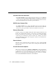
Low Host Processor Overhead The Intellio C320Turbo is equipped with two high performance processors (TMS320) on both the Control Board and the CPU/Basic Module and 512KB on-board memory to relieve the host’s CPU workload of all data and I/O handling tasks. The memory buffer holds transmitted and received data to prevent data loss.
Introduction UART Module UART Module CPU Module 1 1 3 3 4 4 5 6 5 6 7 7 8 8 Extensive Module DB25 to DB25 Cable C320 Turbo Basic Module Surge/Isolation Protection To prevent the boards from damage caused by lightning or high potential voltage, TVSS (Transient Voltage Surge Suppressor) and high potential difference protector technologies are introduced in some connection options to protect the multiport controller.
(API-232). Users can use this library to develop your own applications using Visual C++, Visual Basic, Borland C++, Borland Delphi, Microsoft C, Turbo C, Assembly, QuickBASIC, Turbo Pascal, Clipper, etc. Utilities, such as Data Scope, monitor, terminal emulation, diagnostics, etc., are included for debugging or monitoring the communication status or terminal emulation or even file transferring. Easy Installation No matter hardware or software, installation are made as easy as possible.
Introduction Windows 3.x, Linux, OS/2 and QNX. v Friendly user interface for configuration and utilities v Powerful and easy serial programming library and illustrative examples Check List Upon unpacking Intellio C320Turbo package, the following items are included: One Intellio C320Turbo Control Board One CPU Module or Basic Module One 2-meter DB25 to DB25 cable for connecting Control Board and CPU/Basic Module.
Installation Guide This section gives a brief summary of how to install the Intellio C320Turbo under each supported operating system. Installation is simple and involves the following stages: Set IRQ, memory address for the board Install Intellio C320Turbo board and connection option (cable/box) See Chapter 2 Install software from diskette and configure driver for board and ports See respective O.S.
2 2 Hardware Installation The installation of I n t e l l i o C320T u r b o consists of hardware installation and software installation. For software installation, please refer to the respective section of operating systems in the next chapter. Hardware installation is stated in this chapter. The Intellio C320Turbo hardware installation consists of Control Board installation and external module installation. Make sure you have connected the Control Board with proper number of external modules .
JP1 (ON: install jumper) 1 ON OFF OFF OFF OFF OFF OFF OFF OFF Step 4: 2 OFF ON OFF OFF OFF OFF OFF OFF OFF 3 OFF OFF ON OFF OFF OFF OFF OFF OFF 4 OFF OFF OFF ON OFF OFF OFF OFF OFF 5 OFF OFF OFF OFF ON OFF OFF OFF OFF (*: default) 6 OFF OFF OFF OFF OFF ON OFF OFF OFF 7 OFF OFF OFF OFF OFF OFF ON OFF OFF 8 OFF OFF OFF OFF OFF OFF OFF ON OFF 9 OFF OFF OFF OFF OFF OFF OFF OFF ON IRQ 2 3 4 5 7 10* 11 12 15 Choose a base address (occupying 16KB) which is not used by expansion memory or other add-in b
Hardware Installation slot. Step 7: Fasten the holding screw to make the Control Board fixed. Step 8: Replace the system cover. Now the installation of the Control Board is complete. Continue to install the external modules. Installing the External Modules There are two major connection options for the installation of external modules: CPU and UART Modules for Desktop option or Basic and Extensive Modules for Rackmount option .
A: Set the CPU Module power switch to the OFF position. This is absolutely necessary when installing or removing the cable, the CPU Module or the UART Module(s). Power should not be switched on until you installed all components. B: Plug the DB25 male end of the shipped 2-meter 25-signal-pin cable into the connector on the rear panel of the Intellio C320Turbo Control Board. Refer to the chapter 5 for the cable pinouts details.
Hardware Installation C320Turbo Control Board. C320 Turbo Control Board 10-signal-pin Cable 1 1 2 2 3 3 4 4 5 5 6 6 7 7 8 8 00 Power Adapter UART Module C: UART Module CPU Module Plug the other DB25 female end into the CPU Module's DB25 connector. Warning! Do not use a 25-signal-pin cable to connect the Intellio C320Turbo Control Board to the CPU Module when using the power adapter as this will cause power crash.
Step 10: Connect the first UART Module to the CPU Module. Connect the second UART Module to the first one if necessary and so on. Metal Plate Screws To Control Board UART Module UART Module CPU Module For better fixation of modules, Fixing Kit is available and see the bottom view of modules below to install. Step 11: After making sure that each component has been correctly installed, you are recommended to power on the CPU Module first and then power on the PC system secondly.
Hardware Installation Extensive Module 25-singal-pin Cable Basic Module C320 Turbo Control Board A: Set the Basic Module power switch to the OFF position. This is absolutely necessary when installing or removing the cable, the Basic Module or the Extensive Module(s). Power should not be switched on until you installed all components. B: Plug the DB25 male end of the shipped 2-meter 25-signal-pin cable into the connector on the rear panel of the C320Turbo Control Board.
C: Control Board. Plug the other DB25 female end into the Basic Module's DB25 connector. Warning! Do not use a 25-signal-pin cable to connect the Intellio C320Turbo Control Board to the Basic Module when using the power adapter as this will cause power crash. (One power comes from the power adapter while the other power comes from the Intellio C320Turbo Control Board) D: Connect the power adapter to the Basic Module. Keep the Basic Module's power switch at the OFF position.
Hardware Installation L-type Plate L-type Plate Multiport Controller with Rack Mount Kit installed ( Rear View ) Screw l Now the installation of the external Basic/Extensive module is complete. Continue to install the software driver explained in chapter 3. Operating LED Indicators After completing the installation and powering on the CPU/Basic Module and the PC system, check the two-digit LED display on the CPU/Basic Module.
T R D D R C D X X T S T T C D D R R S S D 48 MODULE CHANNEL CPU Module Basic Module The left digit shows the number of 8-port unit that configured (if continuous 8 ports are considered as an 8-port unit) and the right digit shows the last port number within an 8-port unit. For example, if “48” is displayed, it means that the last accessible port is the eighth port of the fourth 8-port unit.
Hardware Installation Mix of Various UART Modules UART Modules with various functions are produced for different requirements, such as RS-232/RS-422, female/male DB25 connector, isolation protection or surge protection. No matter what interfaces they use, any two UART Modules could be mixed (connected) together freely depending on needs. For example, users may put 2 male RS-232 UART Modules and 2 female RS-422 UART Modules together for application consideration.
2-12 Intellio C320Turbo User's Manual
3 3 Software Installation In this chapter, software driver installation, configuration and driver upgrade/removal procedures are described for various operating systems, including Windows NT, Windows 95/98, UNIX, DOS and Windows 3.x. Before proceeding with software installation, hardware installation detailed in previous chapter should be completed in advance. However, if you need to develop applications, please refer to the next Chapter, “Serial Programming Tools ” for more information.
Installing Driver The following is the procedure for installing the Intellio C320Turbo driver for the first time under Windows NT 4.0. 1. Please Login NT as Administrator. 2. Open the [Control Panel], click on the [Network] icon and select the [Adapters] tab. 3. Click on the [Add] button, then [Have Disk...] button in “Select Network Adapter”. 4. Specify the exact path of the driver diskette, A:\WINDOWS.NT. Then click on [OK] button.
Software Installation 5. Select “MOXA Intellio Family Multiport Board” in the “Select OEM Option” dialog box, and then click [OK] to enter the “MOXA Configuration Panel” dialog box to start the installation. 6. In the “MOXA Configuration Panel” dialog box, click [Add] to enter “Property” dialog box to add the Intellio C320Turbo board. Select the “C320 Turbo” in the “Board Type” field and choose the appropriate one, C8000 to DC000, in the “Memory Bank” field, appropriate one, 2 to 15, in the “Interrupt No.
7. In the “Property” dialog box, click [Port Setting] to enter the “Individual Port Setting” dialog box to change the port COM number mappings. You have to set up all the ports of the board with the desired “COM number”, which should not conflict with other COM number in use. In this “Individual Port Setting” dialog box, you may have two ways to map the physical ports to COM numbers depending on the check box “Auto Enumerating COM number”.
Software Installation l Non-sequential Port Mapping: (Disable “Auto Enumerating COM number”) Specify the COM number for individual port. For instance, the second port can be out of sequence, say COM18, while the first port is mapped to COM10. In “Individual Port Setting” dialog, you may click on [Advanced Setting] button to tune the advanced features, “UART FIFO” and “Transmission Mode”, for each port for particular performance requirements.
l Transmission Mode Hi-Performance Mode: This feature is set to “Hi-Performance” by default, which accelerates the reaction of data writing behavior by utilizing buffering technology. It lets your communication software reach maximum data throughput in large data transmission. Classical Mode: It lets MOXA ports behave like generic COM ports. Transmission for small data packets would be more precisely and reliable. 8.
Software Installation Note ! Please double check if all the Intellio C320Turbo components: Control Board, link cable and external cable/module, are connected and fastened tightly to make sure that the system and the driver start successfully later. 11. After system restarted, you may check the event log issued by MOXA drive to see if the ports of the board are initialized successfully.
1. Open [Control Panel], click [Network] icon and select [Adapters] tab. 2. Select “MOXA Intellio Family Adapter” item in the “Network Adapters:”. 3. Click on [Properties…] button to enter the “MOXA Configuration Panel” dialog box.
Software Installation In this configuration panel, you may: l Click [Property] to enter “Property” dialog box to configure the selected board with the correct “Memory Bank”, “IRQ” and “COM Number”. Please see steps 6 to 8 in the previous section, “Installing Driver”, for more details, except that the “Board Type” field is not supposed to be changed. l Click [Add] to add one more board that is not yet configured in the system.
Windows 95/98 Windows 95/98 supports up to 128 serial ports, from COM1 to COM128. To fully integrate the advanced features of Windows 95/98, multi-process and multi-thread, pure 32-bit Windows 95/98 virtual device port drivers (VxD) compliant with communication driver (VCOMM) are developed for Intellio C320Turbo and other MOXA multiport boards. The drivers conform to Win32 COMM API standard. If you are the first time driver installer, please go directly to the section “Installing Driver”.
Software Installation In this configuration panel, you may: l Click on [Add] button to add one more board that is not yet configured in the system. At most four of combination of Intellio C320Turbo Series boards can be installed together as long as the memory resources are sufficient and available in a system. l Click on [Remove] button to remove the board currently selected from the configured board list. l Click on [OK] button to confirm the configuration changes you made.
In the “Property” dialog, you may click on [Port Setting] button to pop up the following “Individual Port Setting” dialog to change the port COM number mappings.
Software Installation In the “Individual Port Setting” dialog, you may have two ways to map the physical ports to COM numbers depending on the check box “Auto Enumerating COM number”. l Sequential Port Mapping: (Enable “Auto Enumerating COM number”) Specify the COM number of the first port and subsequent ports are mapped to continuous COM numbers. For instance, if first port is mapped to COM10, then second port is mapped to COM11 sequentially.
In the “Advanced Settings” dialog, you may customize the driver with the following two features: l UART FIFO Enable: You can set this feature to “Enable” (default) and gain best performance for the board. Disable: You can set this feature to “Disable” to avoid from data loss when communicating with communication devices using S/W flow control.
Software Installation Note ! The latest configuration will not take effect unless the system restarts. Note ! Please double check if all the Intellio C320Turbo components: Control Board, link cable and external cable/box, are connected and fastened tightly in order to ensure the system and driver will start successfully later. 7. When system restarts, all the error conditions of the board will be popped up onto the screen if any. Otherwise, everything should be fine.
Updating Driver Open [Control Panel] icon, and click on [System] icon, and select [Device Manager] tab. Then select the “Moxa Intellio Multiport Board” entry and the “C320 Turbo” entry. Click on [Property] button and select [Device Driver] tab and then click on [Update Driver…] button. Removing Driver Open [Control Panel] icon, and then [Add/Remove Programs] icon, and then select [Install/Uninstall] tab. Then select and open the “MOXA Intellio Driver” option and then enter [OK] to remove the driver.
Software Installation UNIX There are various UNIX operating systems, such as SCO UNIX, UNIX SVR4.2, and Solaris, etc. Different types of UNIX drivers are required for different UNIXs. Moxa supports device drivers currently for SCO UNIX, UNIX SVR4.2, XENIX and Solaris. In this chapter, driver installation procedure is described. Administration utility, mxadm, is explained, which is for configuration, monitor and terminal emulation.
Follow the instructions prompted to finish the driver installation Copyright (C) 1999 Moxa Technologies Co., Ltd. All Rights Reserved. MOXA UNIX Device Driver Installation Ver. x.x Please select one of the following OS: 1. SCO UNIX 2. UNIX SVR4.2 3. XENIX Select: Please type 1 for SCO UNIX 3.2.x, SCO OpenServer or SCO Open Desktop. Type 2 for UNIX SVR4.2, UnixWare or MITUX. Type 3. for XENIX. Please select one of the devices where the driver diskette/files put: 1. /dev/fd0135ds18 (A: 1.44MB) 2.
Software Installation Then you will be prompted to shutdown the system on your own for kernel rebuilding and you are recommended to do so. Step 7. After system rebooted, please run “mxadm” to configure the board and port settings. Select and open “Basic Configuration” to do basic board and port configuration. You may further optionally select and open “Advanced Configuration” to do advanced settings. Select and open “Board Reset” to reset the driver and board for the latest configuration to take effect.
MOXA TTY Device Naming Convention If the Intellio C320Turbo is successfully configured, there will be two tty devices created for each port at /dev directory: one is non-MODEM tty (e.g. ttya11), and the other is MODEM tty (e.g. ttyA11). The two devices are actually accessing the same port except that the MODEM tty has to check the ON status of DCD signal to be able to open device, and closing device automatically as DCD signal is OFF.
Software Installation To next module P1 P8 From PC /dev/ttya18 /dev/ttya17 /dev/ttya16 /dev/ttya15 /dev/ttya14 /dev/ttya13 /dev/ttya12 /dev/ttya11 DC IN ON/OFF Basic Module Taking 8 port Intellio C320Turbo as an example, /dev/ttya11 1 /dev/ttya12 2 /dev/ttya13 3 /dev/ttya14 4 /dev/ttya15 5 /dev/ttya16 6 /dev/ttya17 7 /dev/ttya18 8 UART Module To Control Board I8 CPU Module Administration Utility “mxadm” You can use the administration utility, mxadm, to change the Intellio C218Tu
Basic Configuration This is to provide basic settings for driver configuration and features. 1. In the “Basic Board Configuration” dialog, you can press Enter in each field to select the desired option. The fields are detailed as follows. Board Type: C218Turbo, C218Turbo/PCI, C320Turbo, C320Turbo/PCI Memory Bank: C8000, CC000, D0000, D4000, D8000, DC000 In the “Basic Configuration” dialog, you should first press Enter in board type field to select board type, C320Turbo.
Software Installation 2. Press PageDown to enter “getty Setting” sub-dialog, there are some noticeable fields for initialize the port for getty usage. You may skip this step if you will not use getty utility. Non-Modem and Modem Baud Rate This field stands for the initial baud rate symbol and hunt sequence for NonModem /Modem tty. It is simply for setting parameters of getty entries in system file /etc/inittab which could also be manually modified by system administrator.
Advanced Configuration This is to provide advanced settings for advanced driver features beyond basic settings described in the previous Basic Configuration. Similarly, in “Board Settings” dialog, board reset utility (described later) is available for the latest configuration to take effect without kernel rebuilding and system reboot. 1. In the “MOXA Board Advanced Configuration” dialog, you can press Enter in each field to select the desired option. The fields are detailed as follows.
Software Installation 2. Press PageDown to enter “Advanced Port Settings” sub-dialog, there are some noticeable fields for initialize the port for advanced usage. You may skip this step if these features are not concerned. Feature In “Port Feature Settings” sub-dialog, port feature [Terminal] is the only choice if On Board Line Discipline is set to “Enable”. This is good for terminal application users.
Three levels, Slow, Normal and Fast, of port response time are designed for user's need. Ports with faster response time will consume more host CPU's resource while slower response consumes less resource. The response time for those ports with normal or slow response can be further tuned by the response level in “Performance Tuning” menu. In addition, if the port feature is set to On-board Line Discipline “Disable” and Feature “Terminal”, response option will be locked at “Slow” level.
Software Installation The board reset utility eliminates the need to shut down the UNIX system to reinitialize the Intellio C320Turbo board with new configuration. Press Enter to start board reset. However, before the board reset is issued, user must make sure that 1. All enabled ports must be disabled. 2. All processes related to the Intellio C320Turbo, including getty or tty monitor, are killed. After board reset, the following message may show if it is successful. MOXA Serial I/O Board (Ver x.
Driver Removal If you want to remove the Intellio C320Turbo device driver and return to your previous system configuration, simply press Enter in this function entry and answer “Y” to confirm. Then the system will be rebuild. This may take some time. If you answer “N”, no action will be taken.
Software Installation DOS With over ten years of professional expertise in serial communications, Moxa provides high-performance DOS device drivers and powerful library functions, which are integrally called DOS API-232. MOXA DOS device driver supports maximum of 256 serial ports. In this chapter, driver installation, setup, loading and unloading procedures are described. Device naming issue is discussed.
After installation is complete, you will be prompted to proceed running setup program. It is strongly recommended to do so.
Software Installation Driver Setup The following are steps for configuring the Intellio C320Turbo boards and setup the driver. Note that it is not intended to illustrate all the convenient functions of the setup programs when configuring the boards. Please refer to the F1 on-line help instructions as running setup program. 1. Run the setup program, BIN\SETUP.EXE, in the API-232 directory. You will see the first “MOXA C218/C320” dialog probably with no board installed if it is the first time configuration.
2. First, press Enter on the board type field to specify the board type, C320T u r b o . 3. Now the default base memory address and IRQ of the desired Intellio C320Turbo board will be shown along with default port number range.
Software Installation Legend Board Type: Ports: Port number: Choose the board type, C320Turbo. The number of ports for C320Turbo, which is 8. This is actually the port ID of each port. The application software will refer to the port by its port number (ID). Duplicated port number is not allowed. Memory Bank: Base memory address of the board. Duplication is not allowed. Interrupt no.: The IRQ number of the board. All C320T u r b o boards will share one same IRQ.
Legend: Some noticeable fields and functions are explained below. On board TxD buf: On board RxD buf: External RxD buf: F5: Group edit: The transmit (output) buffer already allocated on the C320Turbo board for each port. Cannot be altered. The receive (input) buffer already allocated on the C320 Turbo board for each port. Cannot be altered. Extra receive (input) buffer you wish to allocate for each port. This will consume the DOS conventional memory. Default value is 0.
Software Installation Driver Loading Having completed the setup, you can load the driver, “BIN\MX-DRV.EXE”, at the DOS prompt. The driver will detect the Intellio C320Turbo automatically. If the board(s) is(are) detected, a message similar to below will show: API-232 Version x.x MOXA Intellio ISA series communication driver Setup driver … C320 Turbo board 1: Bank [xxx] IRQ x Port [1-8] Device driver setup O.K. It means the Intellio C320Turbo driver is installed properly.
MOXA Serial Port Names Each MOXA serial port is referenced as port number in terms of programming. The port numbers are automatically assigned, once the port numbers are decided when configuring the ports of the board. For example, if 8 ports are configured and the starting port number is 1, then the mapping of serial port numbers will be as depicted in the following picture.
Software Installation Windows 3.x For users who need to implement an industrial control system or data acquisition system in the Windows 3.x environment, Moxa has developed two device drivers and/or library functions under Windows 3.x which is called Windows 3.x API-232. You should find the Dos/Windows 3.x driver diskette along with shipment in addition to API-232 User's Manual. In this chapter, driver installation and configuration procedure are described.
MOXA Windows-compatible COMM Driver Due to the limitations of Windows 3.x operating system itself, only up to 9 COM ports are supported, i.e., COM1 to COM9. Hence, Intellio C320Turbo with 8 ports is a suitable choice. After successful installation, a program group will be created which contains all the useful programs Moxa provided. Restarting of Windows 3.1 system is required for MOXA Standard Windows-compatible COMM Driver after installation. When system restarted, the MOXA COMM Driver is ready to go.
Software Installation COM 2 1 COM 3 2 COM 4 3 COM 5 4 P1 COM 7 COM 8 COM 9 To Control Board To next module COM 6 5 P8 6 From PC 7 COM 8 9 COM 8 COM 7 COM 6 UART Module COM 5 COM 4 COM 3 COM 2 I8 DC IN ON/OFF Basic Module CPU Module Utilities The utility, TTY, is included to help users monitor and debug RS-232 communications under Windows 3.x which can manipulate ports from COM1 to COM9.
standard might not be able to operate MOXA COM ports. For instance, LapLink for Windows accesses I/O address directly which will fail with the Intellio C320Turbo because C320Turbo is accessed via memory instead of I/O port. MOXA Proprietary Windows DLL Driver For MOXA Proprietary DLL Driver, MOXA API-232 library functions are supported for programming, instead of Windows COMM API.
Software Installation 0 1 1 2 2 3 3 4 4 5 5 6 6 7 7 8 UART Module To Control Board I8 CPU Module To next module P1 P8 From PC 7 6 5 4 3 2 1 0 DC IN ON/OFF Basic Module MOXA Windows API-232 Programming MOXA API-232 Library is available for programming under Microsoft Windows 3.x as MOXA Proprietary Windows DLL Driver is installed. API-232 functions, such as sio_open(), sio_read() and sio_write(), could be used in a way that is mostly like DOS API-232 programming.
Visual Basic are supported in the driver file directory after driver installation. In addition, for Windows C language only, there are also Modem Control and File Transfer library available, supporting Hayes compatible modem control as well as ASCII, KERMIT, XMODEM, YMODEM, and ZMODEM file transfer protocol functions. For complete Windows 3.x API-232 function description, see API-232 User's Manual or file API-232.TXT in the API-232 library for more details. The following functions are for Windows 3.x only.
4 4 Serial Programming Tools Moxa supports powerful but easy serial programming library and utilities under Windows NT, Windows 95/98 and UNIX. You will greatly save the developing time with the MOXA Serial Programming Tools. The following sections details the installation, the library and the utilities under various O.S. platforms.
PComm Programming Library The serial communication library is to assist you to develop programs for serial communications for any COM port complying with Microsoft Win32 API. It can ease the implementation of multi-process and multi-thread serial communication programs and hence greatly reduce the developing time. For complete library function description and example programs for Visual C++, Visual Basic and Delphi, please see help file and example programs in P C o m m directory for more details.
Serial Programming Tools Monitor (for MOXA boards under Windows NT Only) A useful port status monitoring program allows you to watch the selected MOXA COM ports’ data transmitting/receiving throughput and communication line status which are updated and displayed on the screen at every time interval. In addition, you may click on one of the specific displayed port in order to see the current communication parameters and status of that port.
Terminal Emulator The Terminal Emulator features multi-windows and supports terminal types of VT100 and ANSI. You can transfer data interactively, send pattern periodically or transfer file using ASCII, XMODEM, YMODEM, ZMODEM and KERMIT protocols.
Serial Programming Tools UNIX Programming the MOXA Ports The system calls that apply to standard tty port also apply to MOXA port since MOXA port conforms to UNIX tty standard. System calls are like open(), ioctl(), read(), write(), close(), etc. Please refer to your UNIX Programmer's Reference manual. However, these system services only provide limited functions and thus may not satisfy the sophisticated programmers’s need.
1. MIBUFED This function let you know how many bytes queued in input buffer when this function is issued. Syntax for SCO UNIX/XENIX #define MIBUFED int count; 0x401 /*number of bytes queued in the buffer */ ioctl(moxa_fd, MIBUFED, &count); Syntax for SVR4.x UNIX/Solaris x86 #include #include #define MIBUFED struct strioctl ioc; int count; 0x401 /*number of bytes queued in the buffer */ ioc.ic_cmd = MIBUFED; ioc.ic_timout = 0; ioc.ic_len = sizeof(int); ioc.
Serial Programming Tools #include #define MOBUFED 0x402 struct strioctl ioc; int count; /* number of bytes queued in the output buffer */ ioc.ic_cmd = MOBUFED; ioc.ic_timout = 0; ioc.ic_len = sizeof(int); ioc.ic_dp = (char *)&count; ioctl(moxa_fd, I_STR, &ioc); Note: See MIBUFED for influence of STREAMS driver. 3. MTCRTS This function, only valid when hardware flow control is turned off (see MHWFLOW), is used to turn RTS on or off.
This function, only valid when hardware flow control is turned off (see MHWFLOW), is used to turn DTR on or off. Syntax for SCO UNIX/XENIX #define MTCDTR #define TurnON #define TurnOFF 0x404 1 0 ioctl(moxa_fd, MTCDTR, TurnON); ioctl(moxa_fd, MTCDTR, TurnOFF); Syntax for SVR4.x UNIX/Solaris x86 #include #include #define MTCDTR #define TurnON #define TurnOFF struct strioctl ioc; int 0x404 1 0 setting; setting = TurnON /* or TurnOFF */; ioc.ic_cmd = MTCDTR; ioc.
Serial Programming Tools of the output buffer. Each port's output buffer depends on the number of total ports. See below. Model Output buffer/each port C320Turbo w/8 ports C320Turbo w/16ports C320Turbo w/24ports C320Turbo w/32ports 32K bytes 16K bytes 8K bytes 4K bytes Syntax for SCO UNIX/XENIX #define MLOWATER int lowater; 0x405 /* low water value of output buffer (default = 512 bytes) */ ioctl(moxa_fd, MLOWATER, lowater); Syntax for SVR4.
#define MSTATUS #include #include struct strioctl int status; 0x407 ioc; /* status = RS-232 line status /* bit0-CTS (1:on, 0:off) */ /* bit1-DSR (1:on, 0:off) */ /* bit2-DCD (1:on, 0:off) */ */ ioc.ic_cmd = MSTATUS; ioc.ic_timout = 0; ioc.ic_len = sizeof(int); ioc.ic_dp = (char *)&status; ioctl(moxa_fd, I_STR, &ioc); 7. MHWFLOW This function is used to enable/disable hardware flow control.
Serial Programming Tools #define CTSFlowControlBitOn #define RTSFlowControlBitOn #define HWFlowControlOn struct strioctl int 0x01 0x02 0x03 ioc; setting; setting = CTSFlowControlbitOn; ioc.ic_cmd = MHWFLOW; ioc.ic_timout = 0; ioc.ic_len = sizeof(int); ioc.
Utilities You can use the administration utility, mxadm, to monitor port activity and to do terminal emulation, which are details as follows. Port Monitoring This utility gives you a quick view about all the MOXA ports’ activities. You can easily learn each port’s total received/transmitted (Rx/Tx) character count since the time when the monitoring is started. Rx/Tx throughputs per second are also reported in interval basis (e.g.
Serial Programming Tools Press Enter on the port, that the cursor stays, to view the port’s communication parameters, signal status, and input/output queue. Terminal Emulator This utility provides data sending and receiving ability of all tty ports, especially for MOXA ports. It is quite useful for testing simple application, for example, sending AT command to a modem connected to the port or used as a terminal for login purpose.
1. Select and Press Enter on item “Communication Setup” to setup up all the communication parameters for connection. 2. Select and enter “Terminal” to enter terminal emulation. Or select and enter “Advanced Transfer Modes” to perform pattern or file transfer with protocols such as ZModem.
Serial Programming Tools DOS Installation API-232 Library is the professional serial programming tool for DOS. It is installed automatically along with the MOXA DOS drivers. The installation is detailed in Chapter “Software Installation”. DOS API-232 Library DOS API-232 library supports languages like Microsoft C, Turbo C, Macro Assembly, QuickBasic, Turbo Pascal, Clipper, etc. Sample programs for each supported language are included, and placed in the sub-directory ..
There are three major functions in Data Scope utility: 1. The Data Scope utility offers transparent monitoring of serial communication lines and allows data to be streamed to disk storage for later analysis. 2. The TTY terminal emulation utility allows user to view the signal status and transfer data interactively or files using ASCII, XMODEM, YMODEM, ZMODEM and KERMIT protocols. 3. The Diagnostic test utility provides port connection test with two MOXA ports connected via a properly wired cable.
Serial Programming Tools Before executing it, please remove the Moxa driver in advance via executing “Mxdrv/Q” if the Moxa driver is running in the background.
5 5 Connection Option and Cable Wiring In data communications, the term DTE is Data Terminal Equipment like terminal or PC COM1/2. The term DCE is Data Communication Equipment like modem. Please check the precise pinouts, the following pinouts are typical examples. The UART modules for Desktop option provide both RS-232 and RS-422 connection options, depending on the models of modules you choose. The Basic/Extensive modules for Rackmount option provide merely RS-232 connection options.
UART Module C32045T/71T DB25 Female Connector 2 3 4 5 6 7 8 20 RxD TxD CTS RTS DTR GND DCD DSR 8 7 6 5 4 3 2 20 DSR DCD GND DTR RTS CTS TxD RxD UART Module C32047T DB25 Male Connector 2 3 4 5 6 7 8 20 TxD RxD RTS CTS DSR GND DCD DTR 2 3 4 5 6 7 8 20 DTR TxD RxD RTS CTS DSR GND DCD Type 1: Connecting UART Module to a DTE device.
Connection Option and Cable Wiring Null Modem Cable PC COM2 port, Serial Printer, Terminal, or any DTE Device C32047T C32047T DB25 Male Connector TxD RxD RTS CTS DSR DTR GND DCD DTE Device DB25 Male Connector Cable Wiring 2 3 4 5 6 20 7 8 2 3 4 5 6 20 7 8 PC COM2 port, Serial Printer, Terminal, or any DTE Device C32047T C32047T DB25 Male Connector TxD RxD RTS CTS DSR DTR GND DCD TxD RxD RTS CTS DSR DTR GND DCD DTE Device DB9 Male Connector Cable Wiring 2 3 4 5 6 20 7 8 2 3 8 7 4 6 5 1 RxD TxD
Type 2: Connecting UART Module to a DCE device.
Connection Option and Cable Wiring Type 3: Connecting UART Module to a DTE device with 3-pin wiring. If the “Hardware flow control” feature is set to “ON”, you must loop back (or short) the RTS with CTS and DSR with DTR, DCD on MOXA site, indicated in dash-lines of the following diagrams. If the “Hardware flow control” feature is set to “OFF”, you could just leave RTS, CTS, DSR, DTR, DCD open, ignoring the connection indicated in dash-lines.
PC COM2 port, Serial Printer, Terminal, or any DTE Device C32047T C32047T DB25 Male Connector TxD RxD GND RTS CTS DSR DTR DCD 5-6 Intellio C320Turbo User's Manual DTE Device DB9 Male Connector Cable Wiring 2 3 7 4 5 6 20 8 2 3 5 7 8 4 6 1 RxD TxD GND RTS CTS DTR DSR DCD
Connection Option and Cable Wiring RS-422 Cable Wiring for C32061T/C32065T The following RS-422 UART Modules are designed for Intellio C320Turbo C32061T: C32065T: UART Module providing 8 female RS-422 DB25 ports without isolation protection. UART Module providing 8 female RS-422 DB25 ports with 2000V isolation protection which can prevent damage caused by high potential voltage.
The followings are operation modes for RS-422: RS-422 Point-to-point C32061T/65T 3 TxD+(B) 16 TxD-(A) 2 RxD+(B) 14 RxD-(A) 7 GND RS-422 Device RxD+(B) RxD-(A) TxD+(B) TxD-(A) GND RS-422 Broadcasting C32061T/65T TxD+(B) RxD+(B) TxD-(A) RxD-(A) GND RS-422 Device 1 RxD+(B) TxD+(B) RxD-(A) TxD-(A) GND RS-422 Device N RxD+(B) TxD+(B) RxD-(A) TxD-(A) GND RS-422 with Handshaking C32061T/65T 3 TxD+(B) 16 TxD-(A) 2 RxD+(B) 14 RxD-(A) 7 GND 5 RTS+(B) 13 RTS-(A) 4 CTS+(B) 19 CTS-(A) 5-8 Intellio C320Turbo User's
Connection Option and Cable Wiring RS-422 Impedance Matching When an electrical signal travels through two different resistance junctions in a transmission line, the mismatch will sometimes cause signal reflection. Signal reflection causes signal distortion, which in turn will contribute communication errors. The solution to this problem is to establish the same impedance at the line ends as in the line itself by terminating them with resistors.
RS-232 Cable CN20040 Wiring for C32080T/81T/82T/83T & For Basic/Extensive Modules, only RS-232 interface with RJ-45 female connector is supported. A 1.5-meter male RJ-45 to male DB25 RS-232 testing cable, CN20040, is provided with shipment of the Basic Module. The following RS-232 Basic Modules are designed for Intellio C320Turbo. C32080T : C32081T : Basic Module providing 8 female RS-232 ports. Basic Module providing 16 female RS-232 ports.
Connection Option and Cable Wiring Type 1: Connecting Basic/Extensive Module to a DTE device. CN20030 PC COM2 port, Serial Printer, Terminal, or any DTE Device device C3208xT RJ45 Plug Pin 1 C3208xT RJ45 Jack Connector DCD DSR RTS GND TxD RxD CTS DTR G G DTE Device DB25 Male Connector Cable Wiring 1 2 3 4/7 5 6 8 9 8 20 5 7 3 2 4 6 DCD DTR CTS GND RxD TxD RTS DSR For Rackmount option, this RJ45 to female DB25 RS-232 testing cable (CN20030) is available from Moxa.
Type 2: Connecting Basic/Extensive Module to a DCE device. Cable CN20040 Modem, or any DCE Device C3208xT RJ45 Plug Pin 1 C3208xT RJ45 Jack Connector DCD DSR RTS GND TxD RxD CTS DTR DCE Device DB25 Female Connector Cable Wiring 1 2 3 4/7 5 6 8 9 8 6 4 7 2 3 5 20 DCD DTR CTS GND RxD TxD RTS DSR G For Rackmount option, this RJ45 to male DB25 RS-232 testing cable (CN20040) comes with the Basic Module and is provided for testing. G 4/7 means either line 4 or line 7 can be used for GND.
Connection Option and Cable Wiring Type 3: Connecting Basic/Extensive Module to a DTE device with 3-pin wiring. If the“Hardware flow control” feature is set to “ON”, you must loop back (or short) the RTS with CTS and DSR with DTR, DCD on MOXA site, indicated in dash-lines of the following diagrams. If the“Hardware flow control” feature is set to “OFF”, you could just leave RTS, CTS, DSR, DTR, DCD open, ignoring the connection indicated in dash-lines.
C32020T Link Cable There are two different types of link cables: 25-signal-pin link cable and 10-signalpin link cable. The former is used when there is no external power applied to the external module (CPU/Basic Module). The latter is used when the external power is applied to the external module (CPU/Basic Module) if you have chosen to use Long Rang Extension Kit.
Connection Option and Cable Wiring 10-signal-pin Link Cable (for long range extension only) If the external power adapter is applied to the CPU/Basic Module, you will need to use the 10-pin cable accompanying with the Long Range Extension Kit. The Control Board to CPU/Basic Module should have only 10 signal pins with the following pinouts. Warning! Make the link cable carefully and precisely according to the following pinout, otherwise you will risk damaging the Control Board and CPU/Basic Module. Pin No.
5-16 Intellio C320Turbo User's Manual
6 6 Troubleshooting Common C320Turbo problems and possible solutions are listed below. If you still have problems, contact your dealer or Moxa for help. Or report it using “Problem Report Form” to your dealer at once for technical support. 1. MOXA board not found. Hardware causes and solutions: a. The base address you have selected is conflicting with the BIOS shadow RAM or cache. Please disable the area for board.
e. Sometimes it happens when the total consumption of power in the system is higher than the power supply can provide. Especially when many interface boards including board(s) are plugged in the system. It is recommended to replace the current power supply with higher watt one. Or choose the external power option if Intellio C320Turbo is used. Software Causes and Solutions: a. Under DOS/Windows 3.
Troubleshooting c. IRQ settings of software and hardware do not match. 3. “CPU/Basic Module not found” message. Or CPU/Basic Module can not download firmware from the Control Board. Hardware Causes and Solutions: a. Power off the CPU/Basic Module and Control Board system. Check that the connection cable between the CPU/Basic Module and the Control Board is correct and firmly plugged in on both sides. Power on the CPU/Basic Module and wait until the LED display reads “Ld”. Power on the Control Board system.
Hardware Causes and Solutions: If the error message persists after check, return the unit for repair. As “E0”, “E1” or “A1” occurs, usually you have to turn off and on the CPU Module. If problem persists, the CPU Module might be defective. As “E2” occurs, turn off the CPU Module, firmly connect the UART Modules, and turn the power back on. As “E4” occurs, usually you have to turn off the CPU/Basic Module, then turn on at least time interval 3 seconds.
Troubleshooting Windows NT This section is specific for troubleshooting under Windows NT. For general problems and solutions, please see the previous section, “General Troubleshooting”. 1. After system starts, error message “MOXA C320Turbo Multiport Board #1 addr(XXX): CPU/Basic Module not found!” appears in Event Log. Shutdown the system first and refer to the problem 3 for solutions in the previous section, “General Troubleshooting”. 2.
5. After system starts, error message “MOXA C320Turbo Multiport Board #1 addr(XXX): CPU/Basic module download failure!” appears in Event Log. Shutdown the system first and refer to the problem 3 for solutions in the previous section, “General Troubleshooting”. 6. Windows NT system panic (blue screen). The possible reason is IRQ conflict with other ISA Bus adapters like LAN and SCSI board, RAID controller or system BIOS. 7. Error message “C320tnt.cod file not found!” appears. Error message “C320tnt.
Troubleshooting Windows 95/98 This section is specific for troubleshooting under Windows 95/98. For general problems and solutions, please see the previous section, “General Troubleshooting”. 1. Error message “C320Turbo at base memory [XXX] download failure!” appears. Shutdown the system first and refer to the problem 3 for solutions in the previous section, “General Troubleshooting”. 2. Error message “C320Turbo at base memory [XXX] number of UART Modules mismatch!” appears.
This indicates MOXA board is found but the IRQ is conflicting with other adapter. Make sure there is no conflict with other adapter's IRQ. Check the PCI BIOS IRQ setting and make sure the IRQ is available. 7. Error message “C320twin.cod file not found!” appears. Error message “C320twin.cod file length is wrong!” appears. Error message “C320twin.cod file data content error!” appears. It means something is wrong with driver installation or the file has been deleted accidentally or corrupted somehow.
Troubleshooting appear: “Time out table overflow”, “File table overflow”, “Region table overflow”. The above error messages imply that the system resources are exhausted. You should tune the kernel parameters to a larger value and rebuild the kernel to be able to accommodate the new configuration. Refer to UNIX system manual about how to tune the parameters and rebuild kernel. “Time out table overflow”: NCALL parameter too small. “File table overflow”: NFILE or NINODE parameter too small.
6-10 Intellio C320Turbo User's Manual
Ap p e n d ix A Technical Reference Specifications System v Up to 32 serial ports per Control Board v Up to 4 Control Boards per PC system for a total of 128 ports v Supports device drivers for most popular operating systems. See the driver support list below: C320Turbo/PCI DOS Windows NT Windows 95/98 Windows 3.1 SCO UNIX/OpenServer UNIX SVR4.2 SCO XENIX Solaris x86 OS/2 Linux2.0.x/2.2.
100 m To CPU/Basic Module C320 Turbo CPU Module and UART Module for Desktop Option CPU Module (for Desktop option) v TMS320C52 processor v 16 KB ROM and 32 K Words RAM v Diagnostic LEDs show full status of each serial port, including TxD, RxD, DTR, DSR, RTS, CTS, DCD v Optional power adapter for use when the distance between Control Board and CPU Module is longer than 2 meters. In this case, a 10-signal-pin DB25 to DB25 cable must be used between Control Board and CPU Module.
Technical Reference UART Module (for Desktop option) v RS-232/RS-422 serial ports v 16550C UART chip with 32 bytes FIFO (Tx+Rx) and on-chip hardware flow control v Each UART chip drives one serial port (Max. 460.
Basic Module ( Front View ) Multiport Controller B? a? s?i ?c M ?o?d?u?l ?e Power TxD RxD DTR P9 P16 P1 P8 DSR RTS CTS DCD Module Channel To next module From PC DC IN ON/OFF To Control Board Basic Module ( Rear View ) Extensive Module (for Rackmount option) v 8or 16 RS-232 serial ports v 16550C UART chip with 32 bytes FIFO (Tx+Rx) and on-chip hardware flow control v Each UART chip drives one serial port (Max. 460.
Technical Reference Dual-Ported RAM There is 512 KB of dual-ported DRAM on the Intellio C320Turbo Control Board which is used as a data buffer and memory map device for the motherboard. it is called “dual-ported” because it is accessed by both motherboard CPU and the C320Turbo Control Board's on-board CPU. Generally speaking, the memory access time is much faster than normal I/O access. All messages and data are transferred through this 512 KB dual-ported memory.
SW1 Dip switch settings 1 ON OFF ON OFF ON OFF ON OFF ON OFF ON OFF ON OFF ON OFF ON OFF ON OFF ON OFF ON OFF ON OFF ON OFF ON OFF ON OFF ON OFF ON OFF 2 OFF OFF ON ON OFF OFF OFF OFF ON ON OFF OFF OFF OFF ON ON OFF OFF OFF OFF ON ON OFF OFF OFF OFF ON ON OFF OFF OFF OFF ON ON OFF OFF 3 ON ON OFF OFF OFF OFF ON ON OFF OFF OFF OFF ON ON OFF OFF OFF OFF ON ON OFF OFF OFF OFF ON ON OFF OFF OFF OFF ON ON OFF OFF OFF OFF 4 OFF OFF OFF OFF OFF OFF ON ON ON ON ON ON OFF OFF OFF OFF OFF OFF ON ON ON ON ON ON OFF
Technical Reference The 16550C is an advanced asynchronous controller capable of on-chip hardware flow control and highest speed up to 921.6 Kbps. Inside UART/Basic/Extensive Module, each 16550C chip control one port.
Problem Report Form I n t e l l i o C320 T u r b o Customer name: Company: Tel: Email: Fax: Date: 1. Moxa Product: □ C320 Turbo Serial Number:___________ 2. Moxa Driver Version: ________________ 3. Moxa hardware settings: Memory Bank Address: ________ IRQ: ________ 4. Operating System: □ DOS □ Windows NT 3.51 □ SCO UNIX 3.2.4 □ SVR4.2 UNIX □ OS/2 □ Windows 95 □ Windows 98 □ Windows NT 4.0 □ Windows 3.1 □ SCO OpenServer Release 5 □ SCO XENIX □ (SCO) UnixWare ver _ □ QNX □ Linux 2._.
Technical Reference Intellio C320Turbo User's Manual 9
RETURN PROCEDURE For product repair, exchange or refund, the customer must: v Provide evidence of original purchase v Obtain a Product Return Agreement (PRA) from the sales representative or dealer v Fill out the Problem Report Form (PRF) as detailed as possible for shorter product repair time. v Carefully pack the product in anti-static package, and send it, pre-paid, to the dealer.