C114HI 3 in 1 RS-232/422/485 Industrial Serial Board Apr.
Copyright Notice This documentation is copyrighted by Moxa Technologies Co., Ltd. All rights are reserved. Moxa Technologies reserves the right to make improvements to the products described in this manual at any time without notice. Information provided in this manual is intended to be accurate and reliable. However, Moxa Technologies assumes no responsibility for its use, nor for any infringements of rights of the fourth parties which may result from its use.
Moxa Internet Services Customer’s satisfaction is always our number one concern. To ensure customers get the full benefit of our services, Moxa Internet Services (MIS) have been built for technical support, product inquiry, new driver upgrade, etc. The followings are the services we provide. E-mail for technical support address: support@moxa.com.tw Ftp site for free driver upgrade address: ftp.moxa.com or ftp.moxa.com.tw user ID: ftp password: your_email_address World Wide Web (WWW) for product info.
Table of Contents Chapter 1 1.1 1.2 1.3 1.4 Chapter 2 2.1 2.2 2.3 Chapter 3 3.1 3.2 3.3 Chapter 4 4.1 4.2 4.3 4.4 4.5 4.6 4.7 Chapter 5 5.1 5.2 5.3 5.4 5.5 5.6 5.7 Chapter 6 6.1 6.2 6.3 Chapter 7 7.1 Introduction .........................................................................................1 Features................................................................................................2 Specifications.......................................................................................
7.2 7.3 7.4 7.5 Chapter 8 Chapter 9 9.1 9.2 9.3 Appendix A A.1 A.2 A.3 A.4 A.5 Appendix B Appendix C Appendix D MOXA Serial Port Naming Convention ............................................29 Baud Rate Settings.............................................................................30 DOS API-232 Library and Programming ..........................................30 Data Scope .........................................................................................31 For Windows 3.x Users .............
Chapter 1 Introduction The Smart 3 in 1 Multiport Async Solutions The C114HI is a RS-232/RS-422/RS-458 4-port serial communication interface board. Each port can be configured to RS-232, RS-422 or RS-458 individually. It is designed for the system manufacturers, integrators or VARs that want to provide all high performance, reliability and quality multiple port data communication system.
Introduction l l Chapter 1 1.1 Features The C114HI 4 port RS-232/422/485 board provides the following advanced features: u u u u u u u u u u 16 bit AT bus architecture, more IRQs supported ASIC-designed, easily configured by software ( IO-IRQ/DOS ) Independent I/O address and IRQ settings for each of 4 serial ports 4 high speed, up to 921.
Chapter 1 l l Introduction C114HI Windows NT Windows 95 Windows 3.x DOS Linux OS/2 SCO UNIX/OpenServer SCO XENIX QNX FreeBSD PICK OS MUMPS Multiuser DOS 3/C 3/C 3/C 3/C R/C C C C C C C C C 3: Driver supported by Moxa and shipped with product R : Driver supported by Moxa but shipped by request C : Driver supported by OS Note: MOXA FTP site is available for driver download 1.3 Check List Upon unpacking the C114HI package, you should find the following items included: 1.
Introduction l l 4 Chapter 1
Chapter 2 Hardware Installation and IO-IRQ 2.1 IO-IRQ Configuration Utility Before installing any driver for C114HI in the system, it is necessary to run DOS configuration utility, IO-IRQ.EXE, to configure the ports, such as I/O address, IRQ, Interrupt vector, etc. The utility is in the API-232 (DOS/Windows 3.x) driver diskette. And select "C104 family" for C114HI to configure.
6 C114HI’s Layout JP1 JP6 JP10 RTS ON RTS ON REG REG AUTO AUTO ON ON RTS OFF RTS OFF REG JP4 PORT 3 PORT 1 JP2 REG AUTO AUTO ON ON JP11 JP7 232 422 485 485 422 232 JP8 JP12 RTS ON RTS ON REG REG AUTO AUTO ON ON RTS OFF RTS OFF REG JP5 PORT 4 PORT 2 JP3 REG AUTO AUTO ON ON JP9 JP13 232 422 485 485 422 232 RT2 RT1 RT4 RT3 RT6 RT5 RT7 RT8 PORT 1 PORT 2 PORT 3 PORT 4 Hardware Installation and IO-IRQ l l Chapter 2
Chapter 2 l l Hardware Installation and IO-IRQ 2.2 Jumper Settings for Interface Jumpers for the first and second ports are symmetric with those for the third and forth ports as shown in the above picture. Port 1 JP 2 JP 6 JP 7 Port 2 JP 3 JP 8 JP 9 Port 3 JP 4 JP 10 JP 11 Port 4 JP 5 JP 12 JP 13 Selection Function Interface & RS-485 Operation Mode RS-422/RS-485 Transmitter Mode RS-422/RS-485 Receiver Mode For illustration, jumper settings of the first port is shown below.
Hardware Installation and IO-IRQ l l AAAA AAAAAAAA AAAAAAAA AAAAAAAA AAAA AAAAAAAA AAAAAAAA AAAAAAAA AAAAAAAA AAAAAAAAAAAA AAAAAAAAAAAA AAAAAAAA AAAAAAAA AAAAAAAA AAAA AAAAAAAA AAAAAAAA AAAAAAAA AAAAAAAA AAAAAAAAAAAA AAAAAAAAAAAA AAAA AAAAAAAA AAAAAAAAAAAA AAAAAAAAAAAA AAAAAAAA AAAAAAAA AAAA AAAAAAAA AAAAAAAA AAAAAAAA AAAAAAAA AAAAAAAAAAAA AAAAAAAAAAAA AAAA AAAAAAAA AAAAAAAAAAAA AAAAAAAAAAAA AAAAAAAAAAAA AAAAAAAAAAAA AAAA AAAAAAAA AAAAAAAA AAAA AAAAAAAA AAAAAAAA AAAAAAAA AAAAAAAA AAAAAAAAAAAA AAAAAAAAAAA
Chapter 2 l l Hardware Installation and IO-IRQ Half Duplex Operation Mode AAAA AAAAAAAA AAAAAAAA AAAAAAAAAAAA AAAAAAAAAAAA AAAAAAAA AAAAAAAA AAAA AAAAAAAA AAAAAAAA AAAAAAAAAAAA AAAAAAAAAAAA AAAAAAAA AAAAAAAAAAAA AAAAAAAA AAAAAAAA AAAA AAAAAAAA AAAAAAAA AAAAAAAAAAAA AAAAAAAAAAAA AAAAAAAA AAAAAAAAAAAA AAAAAAAA AAAAAAAA AAAA AAAAAAAA AAAAAAAA AAAAAAAAAAAA AAAAAAAAAAAA AAAA AAAAAAAA AAAAAAAAAAAA AAAA AAAAAAAA AAAAAAAA AAAAAAAA AAAAAAAA AAAA AAAAAAAA AAAAAAAA AAAAAAAA AAAAAAAAAAAA AAAAAAAAAAAA AAAA AAAAAAAAAA
Hardware Installation and IO-IRQ l l Chapter 2 If you are going to install multiple C114HI boards, configure one board at a time to prevent hardware conflict. Make sure no existing devices have the same I/O address as the CAP address, e.g. 0x180. If so, try to avoid the conflict by doing either one of the following (a or b). a. Short the jumper at position JP1 on the upper-left corner of C114HI. This will force the CAP address to 0xA700. b. Change or disable the existing board's I/O address.
Chapter 3 Software Installation The C114HI boards are compatible with various operating systems such as SCO UNIX/XENIX, OS/2, QNX, PICK OS, MUMPS, Linux, and IMS Multiuser DOS. Please refer to the relative operating system's manual for how to configure the board. The C114HI boards support Windows NT, Windows 95, DOS and Windows 3.x device drivers. The compatible SCO UNIX/XENIX and OS/2 drivers are also described in this Chapter. 3.1 Windows NT/95, DOS/Windows 3.
Software Installation l l Chapter 3 The screen will show: You would like to install a: 1. 1 port card 2. 2 port card 3. 4 port card 4. ...... Enter number 3 to choose "4 port card". The screen then shows: The card is configured as: 1. COM1 2. COM2 3. COM3 4. COM4 For first C114HI 4 port board, choose number 1 (COM1); for second, number 2 (COM2). Then the screen shows like: Which card do you have? 1. Arnet base address 0xaaa 2. Arnet base address 0xbbb 3. Hostess base address 0xccc 4. ......
Chapter 3l l Software Installation OS/2 or by the COM.SYS device driver provided by Device Driver Source Kit for OS/2. COM.SYS Default Device Driver The default device driver can only apply to standard COM1 and COM2 ports. It is active when the system is booted up. Please configure the first and second ports of the C114HI as COM1 (3F8, IRQ4) and COM2 (2F8H, IRQ3), respectively. Interrupt vector is not used. Remember to disable the COM1/COM2 on the host if exist. COM.
Software Installation l l 14 Chapter 3
Chapter 4 For Windows NT Users In this chapter, software driver installation, configuration and upgrade/removal procedure are described. If it is necessary for you to develop your own applications, we strongly recommend the easy but powerful PComm serial comm tool, which includes library for easy programming and useful utilities for diagnostic and monitor. Finally, Windows NT-specific troubleshooting is included. 4.
For Windows NT Users l l Chapter 4 4.2 Board and Port Configuration The following is the procedure for configuring the C114HI driver under Windows NT 4.0 (or NT 3.51): 1. Enter [Control Panel] group, then select [Network] icon, and then [Adapters] folder. (Enter [Control Panel] folder, then select [Network] icon for NT 3.51.) 2. Select "MOXA C102/C104/C168 Adapter" item for "Installed Adapter Cards:", then [Configure/Properties] button to start the "MOXA C102/C104/C168 Family Configuration Panel" dialog.
Chapter 4 l l For Windows NT Users and subsequent ports are mapped to continuous COM numbers. For instance, if the first port is mapped to COM10, then the second port is mapped to COM11 sequentially. For receive FIFO trigger level (bytes), every port will have the same trigger level as set. For 16550-compatible type of UART, receive FIFO trigger level is 1, 4, 8 or 14 bytes. The default is 14 bytes. Non-sequential Port Mapping: For I/O Address, set the I/O address of each port independently.
For Windows NT Users l l Chapter 4 To upgrade driver, remove the installed driver first and install the new one. To remove driver, 1. Enter [Control Panel] group, then select [Network] icon, and then [Adapters] folder. (Enter [Control Panel] folder, then select [Network] icon for NT 3.51.) 2. Select "MOXA C102/C104/C168 Adapter" in adapter list, then [Remove] button to start removing the MOXA board. 4.
Chapter 4 l l For Windows NT Users checking the following items: - Plug in the board(s) properly. Inspect carefully on the settings of I/O address for each board installed. Sometimes slot for plugging board is malfunctioned. In this case, please try other slots until good one is found. The board might be defective. For "quick installation" users, make sure the jumper JP1 is always short and the additional I/O address 0xA700 is not occupied by other devices.
For Windows NT Users l l 20 Chapter 4
Chapter 5 For Windows 95 Users In this chapter, software driver installation, configuration and removal procedure are described. If it is necessary for you to develop your own applications, we strongly recommend that try out the easy but powerful PComm serial comm tool, which includes MOXA serial communication library for easy programming and utilities for diagnostic and monitor. Finally, Windows 95-specific troubleshooting is included. 5.1 Driver Installation - Setup95.exe 1. Run Setup95.
For Windows 95 Users 5 l l Chapter Click [Properties] button to set up a board with correct "Board Type", "IRQ", "INT Vector", "I/O Address", "COM Number" and "Received FIFO Trigger Level", where the possible parameters are as follows: Board Type: C104, C168 Family. IRQ: 2, 3, 4, 5, 7, 10, 11, 12, 15. INT Vector: I/O address for interrupt vector from 00000H to 0FFFFH. To use INT vector, type in the hardware INT vector I/O address. If not using INT vector, type 0 or leave blank as the INT vector.
Chapter 5 l l For Windows 95 Users 5.3 Board Initialization Status Checking All the error conditions, during the initialization of Windows 95, will be popped up onto the screen. Otherwise, everything should be fine. If message like "Can not find the configured C102/C104/C168 (CAP=0xXXXX) !" or "The C102/C104/C168's software and hardware configuration mismatch (CAP=0xXXXX) !" shows, refer to Section "Troubleshooting" for solutions. 5.
For Windows 95 Users 5 l l Chapter The error messages and solutions are stated as clearly as possible. If all the possible solutions fail, the board or connection box might be defective. Please check the board or connection box ONE AT A TIME in the system and find out the defective one. 1.
Chapter 6 PComm PComm, the professional serial comm tool for PC, is a software package under Windows NT/95, which consists of powerful serial communication library for easy programming in most popular languages, useful utilities such as diagnostic and monitor, illustrative example programs and comprehensive on-line documents.
Chapter 6 l l PComm help in the diskette. Diagnostic A convenient diagnostic program provides internal and external testing, such as IRQ, TxD/RxD, UART, CTS/RTS, DTR/DSR, DTR/DCD testing, etc., for the MOXA boards and ports to verify correct operation of both the software and hardware.
Chapter 7 For DOS Users The C114HI is useful for office automation and industrial control as well as data acquisition and communication. Because many users need to implement an industrial control system or data acquisition system in the DOS environment, but DOS did not have any better communication API, thus Moxa has developed device drivers and library functions under DOS. Furthermore, Data Scope utility is very helpful for troubleshooting and debugging the serial communications.
For DOS Users l l Chapter 7 before running SETUP program, execute Io-irq to designate I/O address and IRQ. 2. Choose "C102/C104/C168 Series Multiport Board" in the "DRIVER SELECTION" dialog and then enter or modify each port's configuration which are the port initial value when driver is loaded. 3. Use F8 function to load the on-board configuration for Smartio C104/C168 Family. Use other functions to modify settings if necessary. Finally remember to use F10 function to save the configuration.
Chapter 7 l l Interrupt number: For DOS Users The IRQ number of each port. Several ports may share one common IRQ. TxD buffer size: The transmit (output) buffer reserved for the port. RxD buffer size: The receive (input) buffer reserved for the port. Driver Loading Having completed the setup, load the driver, BIN\SER-DRV.EXE, at the DOS prompt. The driver will detect the multiport board automatically.
For DOS Users l l Chapter 7 For example, if 4 ports are configured and the starting port number is 1, then the mapping of serial port numbers will be as depicted. 1 C114HI 3 2 4 7.3 Baud Rate Settings Be aware that, for Smartio boards configured as High Speed Spectrum, the real working speed is equal to 8 times of the displayed speed. For example, a port, if set to Normal Speed Spectrum with 38.4 Kbps, will work at 38.4 Kbps for sure; while a port, if set to High Speed Spectrum with shown speed 38.
Chapter 7 l l For DOS Users 7.5 Data Scope The Data Scope, BIN\SCOPE.EXE, is a suite of utility programs that can help users with system troubleshooting and serial communication debugging. There are three major functions: 1. The Data Scope utility offers transparent monitoring of serial communication lines and allows data to be streamed to disk storage for later analysis. 2.
For DOS Users l l 32 Chapter 7
Chapter 8 For Windows 3.x Users MOXA API-232 is a software package that assists users to develop and/or debug programs for serial communications under Windows 3.x (and also DOS). In this chapter, driver installation and configuration procedure are described. Utility, TTY, is explained, which is good for terminal emulation. Related issues such as driver removal, baud rate settings, programming and existing applications are also stated. Installation To install, run WININST.EXE in the DOS/Windows 3.
For Windows 3.x Users l l Chapter 8 Due to the limitations of Windows 3.x operating system itself, only up to 9 COM ports are supported, i.e., COM1 to COM9. Hence, C104 with 4 ports or other 4 port non-intelligent boards, maximum 6 ports is supported if the existing standard COM ports (COM1 and COM2) are included. After successful installation, the MOXA program group will be created which contains all the useful programs Moxa provided. Restarting Windows 3.
Chapter 8 l l For Windows 3.x Users Windows 3.x COMM API Programming MOXA Windows-compatible COMM Driver supports Microsoft Windows COMM API such as OpenComm(), ReadComm(), WriteComm(), etc. It supports any language conforming to the Windows COMM API like Microsoft C, Borland C, Visual C, Visual Basic, Delphi, etc. Sample programs for only Microsoft C, Borland C and Visual Basic are supported. For other languages' sample programs, please refer to the language-provided communication example programs.
For Windows 3.
Chapter 9 RS-232/422/485 Programming The C114HI could be used for RS-232, RS-422 or RS-485 communications. It comes with a high level RS-232 Application Programming Library, API-232, for serial communication control under DOS, Windows 3.x, Windows NT and Windows 95. With proper jumper settings and cable wiring, users can program as follows : 9.1 RS-232 Programming Please refer to the API-232 User's Manual or the documentation file \API-232.TXT in the API-232 or Windows NT/95 driver diskette. 9.
Chapter 9 l l RS-232/RS-422/RS-482 Programming outportb(BASE + 4, 3); Or use the following function in API-232 library: sio_RTS(port, 1); A statement as following will clear the RTS signal and turn off the transmitter : outportb(BASE + 4, 0); Or use the following function in API-232 library: sio_RTS(port, 0); Besides, the following function in API-232 library is provided especially for RS-485 programming: sio_putb_x(); Please refer to API-232 User's Manual for more details. 2.
RS-232/RS-422/RS-482 Programming l l Chapter 9 A statement as following will turn on both the transmitter and the receiver: outportb(BASE + 7, 3); 3. AUTO In the AUTO mode, the transmitter is enabled and the receiver is disabled whenever outgoing data is available. Otherwise, the transmitter is disabled and the receiver is enabled. No handshaking signals, such as RTS, are necessary. Users can build a RS-485 network with just two wires. The RS-485 control is completely transparent to users.
Chapter 9 l l 40 RS-232/RS-422/RS-482 Programming
Appendix A Pinouts and Cable Wiring C114HI is suitable for RS-232, RS-422 or RS-485 communications. Each port can be set to RS-232, RS-422 or RS-485 interface independently via the jumpers. Refer to Chapter "Hardware Installation and IO-IRQ" for more details. In data communications, the term DTE is Data Terminal Equipment like terminal or PC COM1/2. The term DCE is Data Communication Equipment like modem. Their precise pinouts and cable wiring are as follows.
Appendix A l l GND 5 DTR 4 TxD 3 RxD 2 DCD 1 9 8 7 6 RI CTS RTS DSR Pinouts and Cable Wiring NC 10 5 GND RI 9 4 DTR CTS 8 3 TxD RTS 7 2 RxD DSR 6 1 DCD RS-232 cable wiring is as follows: Type 1: To connect C114HI to a DTE. C114HI DB-9 Male DTE DB-25 Male C114HI DB-9 Male DTE DB-9 Male 3 2 7 8 6 4 5 1 3 2 5 4 20 6 7 8 3 2 7 8 6 4 5 1 2 3 8 7 4 6 5 1 TxD RxD RTS CTS DSR DTR GND DCD RxD TxD CTS RTS DTR DSR GND DCD Type 2: To connect C114HI to a DCE.
Pinouts and Cable Wiring l l Appendix A Type 3: To connect C114HI to a DTE with 3-pin wiring. If [Hardware flow control] feature is set to "ON", user must loop back (or short) the RTS with CTS and DSR with DTR, DCD on MOXA site.
Appendix A l l Pinouts and Cable Wiring A.2 RS-422 The following lists pinouts of the RS-422 port.
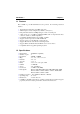
Pinouts and Cable Wiring l l Appendix A A.3 RS-485 The pinouts of the RS-485 port are the same as RS-422 except that only TxD+, TxD-, RxD+, RxD- and GND are used. The following lists pinouts of the RS-422 port. C114HI DB-9 Male Connector 1 2 3 4 5 G 5 Rx 4 Tx 3 Rx 2 Tx 1 C114HI Pin-head Connector TxD-(A) RxD+(B) TxD+(B) RxD-(A) GND 1 2 3 4 5 TxD-(A) RxD+(B) TxD+(B) RxD-(A) GND 10 9 8 7 5 GND 9 4 RxD- 8 3 TxD+ 7 2 RxD+ 6 1 TxD- 6 There are two operation modes for RS-485.
Appendix A l l Pinouts and Cable Wiring 2. Multidrop Multidrop configuration means that more than two devices can be linked together to communicate one another via RS-485 interface. In this configuration, one of the device serves as master device while the rest of the devices as slaves.
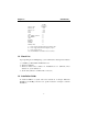
Pinouts and Cable Wiring l l Appendix C114HI site Remote site TxDTxD+ RxD+ RxDRTSRTS+ CTS+ CTSNote: 1. 2. 3. A RxDRxD+ TxD+ TxDCTSCTS+ RTS+ RTS- stands for termination resistor near the receiving side The suggested termination resistor for AWG #26 cable is 100 ohm. The suggested termination resistor for phone cable is 100 ohm. For C114HI, RT1 to RT8 reserved on the board are to be used to install termination resistors for impedance matching. These resistors are not installed at the factory.
Appendix A l l Pinouts and Cable Wiring A.5 Pinouts of DB-37 Connector The following lists pinouts of the C114HI DB-37 connector on the bracket. 1 Note: TXD2-/DCD2 2 GND2 3 CTS2+/CTS2 4 RXD2+/RXD2 5 CTS3-/RI3 6 RXD3-/DTR3 7 RTS3-/DSR3 8 RTS3+/RTS3 9 TXD3+/TXD3 10 TXD3-/DCD1 11 GND1 12 CTS2+CTS1 13 RXD2+/RXD1 14 CTS0-/RI0 15 RXD0-/DTR0 16 RTS0-/DSR0 17 RTS0+/RTS0 18 TXD0+/TXD0 19 20 21 22 23 24 make shield grounded to the connector.
Appendix B High Speed Operations This section describes the use of high speed capability supported by C114HI. There are two speed spectra which are Normal Speed Spectrum High Speed Spectrum 50 75 110 134.5 150 300 600 1200 1800 2400 4800 7200 9600 19200 38400 57600 115200 400 600 880 1076 1200 2400 4800 9600 14400 19200 38400 57600 76800 153600 307200 460800 921600 The corresponding speed in High Speed Spectrum is exactly eight times the speed in Normal Speed Spectrum.
Appendix B l l High Speed Operations For UNIX Users For the C114HI board configured as High Speed Spectrum, the real working speed is equal to 8 times of the displayed speed (with "stty" command).
Appendix C Troubleshooting 1. Board not found. a. The software base addresses do not match with the hardware ones. b. The base I/O addresses selected conflict with other devices. Avoid it and refer to Appendix E. c. The board is not properly plugged in the system. Reinstall it. d. The board is defective. Return it for repair. 2. Board found but can not transfer data. a. Wrong cable wiring. Correct it. b. Wrong IRQ setting or conflict. Change it. 3.
Appendix C l ú ú ú ú ú l Troubleshooting Enter CAP address 0xA700 to access the board and configure it. Keep in mind the CAP. Exit IO-IRQ and power off PC. Remove the jumper cap on the position JP1. Power on PC.
Appendix D I/O Port Address Map The following is the list of the I/O port address commonly used, which is for preventing I/O address conflict when configuring C114HI.
RETURN PROCEDURE For product repair, exchange or refund, the customer must: v Provide evidence of original purchase v Obtain a Product Return Agreement (PRA) from the sales representative or dealer v Fill out the Problem Report Form (PRF) as detailed as possible for shorter product repair time. v Carefully pack the product in anti-static package, and send it, pre-paid, to the dealer.