A50/A51/A60 Feb.
Part I - A50/A51 RS-232 to RS-422/RS-485 Converter A50/A51 RS-232 to RS-422/RS-485 Bidirectional Converter
Part II - A60 RS-232 Surge Protection A60 RS-232 Surge Protection Converter
Copyright Notice This documentation is copyrighted by Moxa Technologies Co., Ltd. All rights are reserved. Moxa Technologies reserves the right to make improvements to the products described in this manual at any time without notice. Information provided in this manual is intended to be accurate and reliable. However, Moxa Technologies assumes no responsibility for its use, nor for any infringements of rights of the fourth party which may result from its use.
Moxa Internet Services Customer’s satisfaction is always our number one concern. To ensure customers get the full benefit of our services, Moxa Internet Services (MIS) have been built for technical support, product inquiry, new driver upgrade, etc. The followings are the services we provide. E-mail for technical support address : support@moxa.com.tw Ftp site for free driver upgrade address : ftp.moxa.com or ftp.moxa.com.tw user ID : ftp password : your_email_address World Wide Web (WWW) for product info.
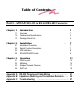
Table of Contents Part I - A50/A51 RS-232 to RS-422/RS-485 Converter Chapter 1. Introduction ………………………………………. 1.1 1.2 1.3 Overview Features and Specifications Package Check List Chapter 2. Installation ……………………………………….. 2.1 2.2 2.3 2.4 Installation Procedure Switch Function Description LED Indicators RS-422/RS-485 Pinouts Chapter 3. Operation ………………………………………… 3.1 3.2 3.3 3.
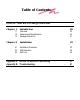
Table of Contents Part II - A60 RS-232 Surge Protection Chapter 1. Introduction…………………………………………… 1.1 1.2 1.3 Overview Features and Specifications Package Check List 29 30 30 31 Chapter 2. Installation……………………………………………… 33 2.1 2.2 2.3 Installation Procedure LED Indicators Self Test Appendix A RS-232 Pinouts and Cable Wiring…………………… Appendix B Troubleshooting ………………………………………..
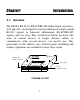
Chapter1 Introduction 1.1 Overview The MOXA RS-232 to RS-422/RS-485 bidirectional converters, A50 and A51, are designed to convert unbalanced (single-ended) RS-232 signals to balanced (differential) RS-422/RS-485 signals, and vice versa. They are the best choices for those who want to control devices at longer distance and/or to communicate with several devices via merely one link, particularly in the industry area. Point-to-point, multidrop and simplex operations are available for most users' needs.
Introduction Chapter 1 Converter IsolatedRS-232toRS-422/485 RS-422/485 RJ-45 Connector A51 A51 RS-422/485 T R R X X T D D S Power Jack P W R RS-232 RS-232 RJ-45 Connector Outlook of A51 1.2 Features and Specifications Features Both A50 and A51 are RS-232 to RS-422/RS-485 bidirectional converters except that A51 has one more feature: isolation protection, which provides high voltage protection up to 2000V.
Chapter 1 Introduction 150mA power adapter or the pin 6 and pin 7 of the Terminal Block. LED indicators are provided to show the status of data transmitting/receiving, RTS signal and Power. To avoid over-current from the remote ground to converter's ground, an protect resistor has been added inside the A50/A51. Specifications v Power Supply - DC +9V to +30V, 150mA Data Rate - Up to 921600 bps under 500 ft (0.15 Km) v Distance - Up to 4000 ft (1.
Introduction v v v Chapter 1 Isolation Protection - for A51 only, up to 2000V. Terminal Resistor - RT1 space reserved for RS-422/RS-485 receiver signal. Mounting Kit - Plastic Plates and screws for mounting A50/A51 on the wall or any surface.
Chapter 1 Introduction 1.
Introduction Chapter 1 6
Chapter 2 Installation 2.1 Installation Procedure As RS-232 or RS-422/RS-485 port are labeled clearly on the surface of the A50/A51 converter, please prepare the RS-232 cable (refer to Appendix A, RS-232 Cable Wiring) and decide the operation mode as well as 2/4-wire cable (refer to Chapter 3, Operation) in advance. Take off the two screws on top of the converter and open the cover up if you need to change the operation mode via sliding the switches. 2.
Chapter 2 l l Installation Switch settings table of SW1 and SW2 is as follows: SW1 *Full-duplex mode Half-duplex mode Off On SW2 *TxD always enabled TxD always disabled TxD enabled by RTS *RxD always enabled RxD enabled by /RTS Pin1 Pin2 Pin3 Pin4 On Off X X Off Off X X Off On X X X X On Off X X Off On Note: ‘ * ‘ means default settings , ‘ X ‘ means don’t care 2.3 LED Indicators There are LED indicators for TxD, RxD, RTS, and PWR on top of A50/A51.
Installation l l Chapter 2 RxD indicator stands for data transmitting from RS-422/RS-485 to RS-232. It shows red when connected and no data received. It shows orange when connected and receiving data (In halfduplex mode, it shows red when line is not connected due to the characteristics of ICs for RS-485). RTS indicator is for RS-232 RTS signal. It shows red when connected and RTS signal turned on. It shows green when connected and RTS signal turned off.
Chapter 2 l l A50/A51 RJ-45 Jack Connector Pinouts Signals 1 2 3 4 5 6 7 8 9 10 nc 1 nc 2 GND 3 TxD B 4 TxD A 5 RxD A 6 RxD B 7 GND nc nc(not connected) Installation A50/A51 Terminal Block Connector Pinouts Signals TxD B TxD A RxD B RxD A GND Power GND Power Input Note : Pin 6 and Pin 7 of Terminal Block are for Power GND and Power Input, which is an alternate option for power adapter. Be careful that DO NOT confuse RS-422/RS485 GND with Power GND.
Chapter 3 Operation The A50 (or A51) supports 5 kinds of operations. They are: v v v v v Point-to-point/4-wire Full Duplex Point-to-point/2-wire Half Duplex Multidrop/4-wire Full Duplex Multidrop/2-wire Half Duplex Simplex/Transmit, Receive Only All the operations are to be described below. And TA, TB, RA and RB represent TxD A, TxD B, RxD A and RxD B signal lines of the RJ-45 RS-422/RS-485 connector or the Terminal Block, respectively.
Chapter 3 l l Operation 3.1 Point-to-point Point-to-point configuration means two devices which locate at two different places can be linked together to communicate through a couple of A50 (or A51) converters. 4-wire Full Duplex A50/A51 DTE/ DCE RS-232 A50/A51 TA RA RS-422/ TB RB RS-422/ RS-485 RB TB RS-485 RA TA GND GND RS-232 DTE/ DCE In the graph, TA, TB, RA and RB could be either from RJ-45 or Terminal Block.
Operation l l Chapter 3 2-wire Half Duplex A50/A51 DTE/ DCE RS-232 RS-485 A50/A51 TA RA TB RB RB TB RA TA GND GND RS-232 DTE/ DCE RS-485 In the graph, TA, TB, RA and RB could be either from RJ-45 or Terminal Block.
Chapter 3 l l Operation 3.2 Multidrop Multidrop configuration means that more than two devices (Max. 10 for RS-422; Max. 32 for RS-485) can be linked all together to communicate one another through many A50 (or A51) devices. In this configuration, one of the A50 (or A51) will be connected to a master device and the rest of A50 (or A51) devices will be connected to any other slave devices.
Operation l l Chapter 3 In the graph, TA, TB, RA and RB could be either from RJ-45 or Terminal Blocks.
Chapter 3 l l A50/A51 Master DTE/ DCE RS-232 RS-485 Operation A50/A51 RA RA TB RB RB TB TA TA GND GND RS-232 Slave DTE/ DCE RS-485 A50/A51 RA RB RS-232 TB TA GND 16 RS-485 Slave DTE/ DCE
Operation l l Chapter 3 In the graph, TA, TB, RA and RB could be either from RJ-45 or Terminal Block. The settings of the switches for each A50 (or A51) are as follows: SW1 Half-duplex mode On SW2 Pin1 Pin2 Pin3 Pin4 TxD enabled by RTS Off On X X RxD enabled by / RTS X X Off On 3.3 Simplex/Transmit, Receive Simplex configuration means that more than two devices (Max. 10 for RS-422; Max. 32 for RS-485) can be linked all together to communicate through many A50/A51 devices.
Chapter 3 l l A50/A51 DTE/ DCE RS-232 Operation A50/A51 TA RA RS-422/ TB RB RS-422/ RS-485 RB TB RS-485 RA TA GND GND RS-232 DTE/ DCE A50/A51 RA RB RS-422/ TB RS-485 RS-232 DTE/ DCE TA GND In the graph, TA, TB, RA and RB could be either from RJ-45 or Terminal Block.
Operation l l Chapter 3 3.4 Self Test This configuration is for A50/A51 self test. Run terminal emulation program to see if what you received is what you typed. A50/A51 TA DTE/ DCE RS-232 TB RB RA RS-422/485 GND In the graph, TA, TB, RA and RB could be either from RJ-45 or Terminal Block.
Chapter 3 l l 20 Operation
Appendix A RS-232 Pinouts & Cable Wiring RS-232 interface with RJ-45 connector is depicted as follows.
Appendix A l l RS-232 Pinouts and Cable Wiring Note : Each group of (RTS, CTS) and (DTR, DSR) pins have been shorted on A50/A51, which release the users from the hardware flow control cable wiring problem. Thus, there are two types of RS-232 cable wiring which are listed below. Type 1: To connect RS-232 side of A50/A51 to a DTE (e.g. PC COM1/2) or DCE .
RS-232 Pinouts and Cable Wiring l l Appendix A50/A51 RJ-45 Connector DCE DB-25 Female 1 2 3 5 6 7 8 9 8 6 4 2 3 7 5 20 DCD DSR RTS TxD RxD GND CTS DTR A DCD DTR CTS RxD TxD GND RTS DSR Type 2: To connect RS-232 side of A50/A51 to a DTE, e.g. terminal or PC COM1/2, with 3-pin wiring if don't care Hardware flow control.
Appendix A l l RS-232 Pinouts and Cable Wiring A50/A51 RJ-45 Connector DCE DB-25 Female 5 6 7 3 8 2 9 1 2 3 7 4 5 6 20 8 TxD RxD GND RTS CTS DSR DTR DCD 24 RxD TxD GND CTS RTS DTR DSR DCD
A p p e n d ix B Im p e d a necM atc h ing a n d T erm in ation Re si sto rs When an electrical signal travels through two different resistance junctions in a transmission line, the mismatch will sometimes cause signal reflection. Signal reflection causes signal distortion, which in turn will contribute communication errors. The solution to this problem is to establish the same impedance at the line ends as in the line itself by terminating them with resistors.
Appendix Bl l Impedance Matching and Termination Resistors Note: 1. stands for termination resistor near the receiving side. RT1 is the space reserved inside A50/A51 for this purpose. 2. The suggested termination resistor for AWG #26 cable is 100 ohm. 3. The suggested termination resistor for phone cable is 600 ohm.
Appendix C Troubleshooting Q1. Failure of data transmission. Solutions: 1. 2. 3. 4. Check that the right power adapter is applied. Check that the RS-232 link is proper. Check that the RS-422/RS-485 link is proper. Check that the SW1 and SW2 are set properly. Q2. Data loss or error. Solution: Check that the data rate, data format are the same for both devices. Q3. How do I do self-test on A50/A51? Solution: Refer to Chapter 3.4 Self Test .
Appendix C l l Troubleshooting ~28~
Chapter 1 Introduction 1.1 Overview The MOXA RS-232 Surge Protection converter, A60, is designed to protect the RS-232 communication line from TOV (Transient Over Voltages) which comes from lightning, electrostatic discharge and other forms. TOV is always the major factor which damages components and makes ports unreliable. To improve this problem, we add Transient Voltage Suppressor to our I/O ports to clamp surge voltage to protect ports from TOV.
Chapter 1 • • Introduction 1.2 Features and Specifications Features A60's main feature is surge protection up to 2000V. No switch is needed. No power is needed. LED indicators are provided to show the status of data transmitting/receiving, modem control signals and DCD.
Introduction • • Chapter 1 Mounting Screw P RS-232 Sur ge A60 Remote rotection T RT DR DR R CP D X X X TX ST T TW C D D RD RS S SR D Local Fixing Screw A60 with Mounting Kit 1.
Chapter 1 • • Introduction ~32~
C hapter 2 Installation 2.1 Installation Procedure Even though the local and remote ports of A60's are labeled on the surface of the A60 converter, please take care when connecting the cables to the A60 and the hosts. Note that the surge from both the local and the remote site is blocked by the A60. However , the LED indicators and the local host are under surge protection if and only if the surge comes in from the remote port of A60.
Chapter 2 • • Introduction 2000 V Surge P A6 0 A6 0 To Remote Host Remote RS-232 Sur ge rotection T R D D R C D X X T S T T C D D R R S S D Local To Local Host Earth Ground Please prepare the RS-232 cables, referring to Appendix A, RS232 Cable Wiring. 2.2 LED Indicators There are LED indicators for TxD, RxD, DTR, DSR, RTS, CTS, and DCD on top of A60. The indicators are not lighted on when not connected with signals.
Installation • • Chapter 2 RxD indicator (signal from remote port ) Green : when connected correctly and no data receiving. Orange : when receiving data from remote to local site. DTR/RTS indicators (signal from local port) Red Green : when connected and DTR (or RTS) signal turned on. : when connected and DTR (or RTS) signal turned off.
Chapter 2 • • Introduction 2.3 Self Test This configuration is for A60 self-test. Run terminal emulation program to see if what you received is what you typed. P RS-232 Sur ge A60 rotection T R D D R C D X X T S T T C D D R R S S D Remote 1 2 3 4 5 6 7 Local In the above graph, all the signal lines could be either from remote site RJ-45 or Terminal Block and shorted as shown.
A ppendix A RS-232 Pinouts and Cable Wiring Below is RS-232 pinouts for RJ-45 connector or Terminal Block.
Appendix A • • RS-232 Pinouts and Cable Wiring There are two types of RS-232 cable wiring which are listed below. Note: 1. Terminal Block supports no DCD signal. 2. DTE: Data Terminal Equipment like terminal or PC COM1/2; DCE: Data Communication Equipment like modem. Please check the precise DTE/DCE pinouts, the following DTE/DCE pinouts is just an example. Type 1: To connect RS-232 local/remote port of A60 to a DTE or DCE.
RS-232 Pinouts and Cable Wiring • A60 DCE DB-25 Female DCD DSR RTS TxD RxD GND CTS DTR 8 6 4 2 3 7 5 20 • Appendix A DCD DTR CTS RxD TxD GND RTS DSR Type 2: To connect RS-232 local/remote port of A60 to a DTE with 3-pin wiring if don't care hardware flow control.
Appendix A • • RS-232 Pinouts and Cable Wiring A60 DCE DB-25 Female TxD RxD GND RTS CTS DSR DTR DCD 2 3 7 4 5 6 20 8 RxD TxD GND CTS RTS DTR DSR DCD ~40~
A ppendix B Troubleshooting Q1. Failure of data transmission. Solutions: Check that the RS-232 link is proper. Q2. Data loss or error. Solution: 1. Check that the data rate, data format are the same for both devices. 2. Surge occurs during the data transferring. Error detection and recovery should be taken in applications. Q3. How do I do self-test on A50? Solution: Refer to Chapter 2.3, Self Test.