MOXA EtherDeviceTM Switch EDS-508 Hardware Installation Guide First Edition, April 2004
MOXA EtherDeviceTM Switch EDS-508 Hardware Installation Guide The software described in this manual is furnished under a license agreement and may be used only in accordance with the terms of that agreement. Copyright Notice Copyright ? 2004 Moxa Networking Co., Ltd. All rights reserved. Reproduction without permission is prohibited. Trademarks MOXA is a registered trademark of the Moxa Group. All other trademarks or registered marks in this manual belong to their respective manufacturers.
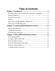
Table of Contents 1 Chapter 1: Introduction ............................................................ 1-1 Why EDS-508 is ideal for Industrial Control and Automation ............... 1-2 Package Checklist........................................................................................... 1-3 Optional Accessories ...................................................................................... 1-3 Features...........................................................................................
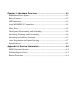
Chapter 4: Hardware Overview ............................................... 4-1 Redundant Power Inputs ................................................................................4-2 Relay Contacts .................................................................................................4-2 LED Indicators.................................................................................................4-3 Auto MDI/MDI-X Connection .................................................................
1 1 Introduction Welcome to MOXA EtherDevice™ Switch EDS-508 , an industrial 8-Port Managed Redundant Ethernet Switches.
Why EDS-508 is ideal for Industrial Control and Automation ? ? Advanced Network Control Function Multicast traffic management— IGMP Snooping function provides the ability to manage multicast traffic. Network segment planning— The VLAN function not only helps to segment your network without being restricted by physical connections, but is also more secure, and protects against unwanted data transmission.
Introduction ? ? Industrial Grade Reliability Extended operating temperature capability— To ensure that your Ethernet equipment can withstand harsh environmental conditions (-40 to 75°C). Industrial strength safety regulations— To ensure that your Ethernet equipment can withstand critical industrial applications, such as in hazardous locations (UL/cUL Class 1 division 2 and ATEX Class1 Zone 2) and comply with FCC, TÜV, UL, and CE Standards.
? ? EDS-SNMP OPC Server: CD with EDS-SNMP OPC Server Software and manual ? ? ADP-SCm-STf-M: Multi-mode SC male to ST female duplex adapter, gray color ? ? ADP-SCm-STf-S: Single-mode SC male to ST female duplex adapter, blue color ? ? WK-46: Wall Mounting Kit Features ?? Advanced Industrial Networking Capability o o o o Redundant Self-Healing Ethernet Ring Capability (recovery time < 300 ms at full load) IGMP Snooping for filtering multicast traffic from industrial Ethernet Protocols Supports IEEE 802.
Introduction o o o -40 to 75°C operating temperature range IP 30, rugged high-strength case DIN-Rail or panel mo unting ability ?? Useful Utility and Remote Configuration o Configurable by Web browser, Telnet/Serial console, Windows utility o Send ping commands to identify network segment integrity MOXA EtherDevice Switch Hardware Installation Guide 1-5
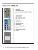
Panel Views of EDS-508 1. 2. 3. 4. 5. 1. 1-6 6. 7. 8. 9. 10. 11. 12. 13. 14. 15. 16. 17. 18. 19.
Introduction Panel Views of EDS-508-MM-SC 1. 2. 3. 4. 5. 6. 7. 8. 9. 10. 11. 12. 13. 14. 15. 16. 17. 18. 19.
Panel Views of EDS-508-SS-SC 1. 2. 3. 4. 5. 6. 7. 8. 9. 10. 11. 12. 13. 14. 15. 16. 17. 18. 19.
2 2 Installing MOXA EtherDeviceTM Switch This chapter includes information about installing MOXA EtherDeviceTM Switch.
Mounting Dimensions 2-2 MOXA EtherDevice Switch Hardware Installation Guide
Installing MOXA EtherDevice Switch DIN-Rail Mounting The aluminum DIN-Rail attachment plate should already be fixed to the back panel of EDS-508 when you take it out of the box. If you need to reattach the DIN-Rail attachment plate to EDS-508, make sure the stiff metal spring is situated towards the top, as shown in the figures below. STEP 1: Insert the top of the DIN-Rail into the slot just below the stiff metal spring. STEP 2: The DIN-Rail attachment unit will snap into place as shown below.
Wall Mounting (Optional) For some applications, you will find it convenient to mount MOXA EDS-508 on the wall, as illustrated below. STEP 1: Remove the aluminum DIN -Rail attachment plate from the MOXA EDS-508 rear panel, and then attach the wall mount plates, as shown in the diagram below.
Installing MOXA EtherDevice Switch STEP 2: Mounting MOXA EDS-508 on the wall requires 4 screws. Use the EDS-508, with wall mount plates attached, as a guide to mark the correct locations of the 4 screws. The heads of the screws should be less than 6.0 mm in diameter, and the shafts should be less than 3.5 mm in diameter, as shown in the figure at the right.
3 3 Wiring MOXA EtherDeviceTM Switch This chapter includes technical information about connecting MOXA EDS-508 to an external power source and to an external alarm system, and shows you what types of cables you should use for the Console port, Ethernet ports, and optical fiber ports.
Wiring Requirements Warning Do not disconnect modules or wires unless power has been switched off or the area is known to be nonhazardous. The devices may only be connected to the supply voltage shown on the type plate. The devices are designed for operation with a safety extra-low voltage. Thus, they may only be connected to the supply voltage connections and to the signal contact with the safety extra-low voltages (SELV) in compliance with IEC950/ EN60950/ VDE0805.
Installing MOXA EtherDevice Switch You should also pay attention to the following items : ??Use separate paths to route wiring for power and devices. If power wiring and device wiring paths must cross, make sure the wires are perpendicular at the intersection point. ??NOTE: Do not run signal or communications wiring and power wiring in the same wire conduit. To avoid interference, wires with different signal characteristics should be routed separately.
Wiring the Relay Contact EDS-508 has two sets of relay output— relay 1 and relay 2. Each Relay Contact consists of the two contacts of the terminal block on EDS-508’s top panel. You may refer to the next section for detailed instructions on how to connect the wires to the terminal block connector, and how to attach the terminal block connector to the terminal block receptor. In this section, we will explain the meaning of the two contacts used to connect the Relay Contact.
Installing MOXA EtherDevice Switch Wiring the Redundant Power Inputs EDS-508 has two sets of power input— power input 1 and power input 2.The top two contacts and the bottom two contacts of the 6-pin terminal block connector on EDS’s top panel are used for dual DC power input. Top and front views of terminal block connectors are shown here. STEP 1: Insert the negative/positive DC wires into the V-/ V+ terminals.
Wiring the Digital Inputs EDS-508 has two sets of digital input, DI 1 and DI 2. Each DI consists of two contacts of the 6-pin terminal block connector on EDS’s top panel, which are used for other device’s digital inputs. Top and front views of the terminal block connectors are shown here. STEP 1: Insert the negative (ground)/positive DI wires into the terminals.
Installing MOXA EtherDevice Switch Communication Connections All models of EDS-508 have one RJ45 console port (RS-232 interface), and between six and eight 10/100BaseTX Ethernet ports. Some models also have two 100BaseFX (SC-type connector) fiber ports.
NOTE 1. The pin numbers for male DB9 and DB25 connectors, and hole numbers for female DB9 and DB25 connectors are labeled on the connector. However, the numbers are typically quite small, so you may need to use a magnifying glass to see the numbers clearly. 2. The pin numbers for both 8-pin and 10-pin RJ45 connectors (and ports) are typically not labeled on the connector (or port). Refer to the Pinout and Cable Wiring diagrams below to see how RJ45 pins are numbered.
Installing MOXA EtherDevice Switch RJ45 (10-pin) to DB9 (F) Cable Wiring RJ45 (10-pin) to DB25 (F) Cable Wiring MOXA EtherDevice Switch Hardware Installation Guide 3-9
10/100BaseTx Ethernet Port Connection The 10/100BaseTX ports located on MOXA EtherDeviceTM Switch’s front panel are used to connect to Ethernet-enabled devices. Most users will choose to configure these ports for Auto MDI/MDI-X mode, in which case the port’s pinouts are automatically adjusted depending on the type of Ethernet cable used (straight-through or cross-over), and the type of device (NIC-type or HUB/Switch-type) connected to the port.
Installing MOXA EtherDevice Switch RJ45 (8-pin) to RJ45 (8-pin) Straight-Through Cable Wiring RJ45 (8-pin) to RJ45 (8-pin) Cross-Over Cable Wiring 100BaseFx Ethernet Port Connection The concept behind the SC port and cable is quite straightforward. Suppose you are connecting devices I and II. Contrary to electrical signals, optical signals do not require a circuit in order to transmit data.
(A-to-A and B-to-B, as shown below, or A1-to-A2 and B1-to-B2).
Installing MOXA EtherDevice Switch SC-Port to SC-Port Cable Wiring This is Class 1 Laser/LED product. To prevent damage to your eyes, do not stare into the Laser Beam.
4 4 Hardware Overview This chapter is an overview of MOXA EDS-508’s various hardware features.
Redundant Power Inputs MOXA EDS-508 has two DC power inputs located on its top panel. For detailed instructions on how to connect the power wires to the terminal block connector, see the Wiring the Redundant Power Inputs section from Chapter 3. From the user’s point of view, the function of the redundant power inputs is quite straightforward. Both inputs can be connected simultaneously to live DC power sources.
Hardware Overview LED Indicators The front panel of MOXA EDS-508 contains several LED indicators. The function of each LED is described in the table below.
On 100M (FX) GREEN Blinking Off FX port’s 100 Mbps is active Data is being transmitted at 100 Mbps 100BaseFX port is inactive Auto MDI/MDI-X Connection The Auto MDI/MDI-X function allows users to connect MOXA EDS-508’s 10/100BaseTX ports to any kind of Ethernet device, without paying attention to the type of Ethernet cable being used for the connection. To understand the meaning of this statement, you simply need to remember that there are two types of Ethernet ports, and two types of Ethernet cables.
Hardware Overview ?? A cross-over cable is used to connect like ports: MDI ? MDI or MDI-X ? MDI-X. For example, you should use a straight-through cable to connect your computer’s Ethernet NIC to a HUB or switch, but use a cross-over cable to connect your computer’s Ethernet NIC to another computer’s Ethernet NIC. Fiber Ports MOXA EDS-508’s fiber switched ports operate at a fixed 100 Mbps speed and full-duplex mode to provide the best performance.
Dual Speed Functionality and Switching MOXA EDS-508’s 10/100 Mbps RJ45 switched ports can be configured for 10 Mbps operation, 100 Mbps operation, or to auto-negotiate with the connected device for the fastest data transmission rate supported by both devices. All models of MOXA EDS-508 are plug-and-play devices, so that software configuration is not required at installation, or during maintenance.
Hardware Overview Switching and Address Learning MOXA EDS-508 has an address table that can hold up to 2K node addresses, which makes it suitable for use with large networks. The address tables are self-learning, so that as nodes are added or removed, or moved from one segment to another, MOXA EDS-508 automatically keeps up with new node locations. An address-aging algorithm causes the least-used addresses to be deleted in favor of newer, more frequently used addresses.
Specifications Technology Standards Protocols Forwarding and Filtering Rate Processing Type Flow Control Address Table Size Management Interface RJ45 Ports Fiber Ports Console LED Indicators Alarm Contact Digital Input 4-8 IEEE802.3, 802.3u, 802.3x, 802.1D, 802.1W, 802.1Q, 802.1p GVRP, SNMP, DHCP Server/Client, BOOTP, TFTP, NTP 148800 pps Store and Forward IEEE802.3x, back pressure 2K uni-cast addresses SNMP V. 1.
Hardware Overview Optical Fiber Distance Wavelength Min. TX Output Max.
Environment Operating Temperature Storage Temperature Ambient Relative Humidity Regulatory Approvals Safety Hazardous Location EMI EMS Shock Freefall Vibration WARRANTY 0 to 60°C (32 to 140°F) -40 to 75°C (for "-T" models) -40 to 85°C (-40 to 185°F) 5% to 95% (non-condensing) UL60950, UL 508, CSA C22.2 No.
A A Service Information This appendix shows you how to contact Moxa for information about this and other products, and how to report problems.
MOXA Internet Services Customer satisfaction is our number one concern, and to ensure that customers receive the full benefit of our products, Moxa Internet Services has been set up to provide technical support, driver updates, product information, and user’s manual updates. The following services are provided E-mail for technical support service@moxanet.com World Wide Web (WWW) Site for product information: http://www.moxa.com or http://www.moxa.com.
Service Information Problem Report Form MOXA EDS-508 Series Customer name: Company: Tel: Fax: Email: Date: 1. Moxa Product: ? EDS-508 ? EDS-508-MM-SC ? EDS-508-SS-SC 2. Serial Number: _________________ Problem Description: Please describe the symptoms of the problem as clearly as possible, including any error messages you see. We may need to follow your description to reproduce the symptoms, so please give a complete description of the problem.
Return Procedure For product repair, exchange, or refund, the customer must: ?? Provide evidence of original purchase. ?? Obtain a Product Return Agreement (PRA) from the sales representative or dealer. ?? Fill out the Problem Report Form (PRF). Include as much detail as possible for a shorter product repair time. ?? Carefully pack the product in an anti-static package, and send it, pre-paid, to the dealer.