MOXA EtherDevice™ Switch EDS-726 Series User’s Manual www.moxa.com/product First Edition, July 2005 Moxa Networking Co., Ltd. Tel: +886-2-2910-1230 Fax: +886-2-2910-1231 Web: www.moxa.com MOXA Technical Support support@moxanet.tw Worldwide: support@moxa.
MOXA EtherDevice™ Switch EDS-726 Series User’s Manual The software described in this manual is furnished under a license agreement and may be used only in accordance with the terms of that agreement. Copyright Notice Copyright © 2005 Moxa Networking Co., Ltd. All rights reserved. Reproduction without permission is prohibited. Trademarks MOXA is a registered trademark of the Moxa Group. All other trademarks or registered marks in this manual belong to their respective manufacturers.
Table of Contents Chapter 1 Introduction ...............................................................................................1-1 Overview .............................................................................................................................. 1-2 Package Checklist................................................................................................................. 1-2 Features .......................................................................................
Configuring 802.1Q VLAN .................................................................................... 3-40 Using Multicast Filtering.................................................................................................... 3-42 The Concept of Multicast Filtering ......................................................................... 3-42 Configuring IGMP Snooping .................................................................................. 3-45 Add Static Multicast MAC...............
1 Chapter 1 Introduction Welcome to MOXA EtherDevice Switch EDS-726 Series, the modular managed Gigabit Ethernet Switch designed especially for connecting Ethernet-enabled devices in industrial field applications.
EDS-726 Series User’s Manual Introduction Overview Network planning is easy and flexible with EDS-726, which has a modular design that lets you install up to 2 Gigabit ports and 24 fast Ethernet ports in one switch. Choose from three 1-port Gigabit modules with copper or fiber optic connectors, and eight 4-port Fast Ethernet modules with copper or fiber optic (SC/ST) connectors. EDS-726 is suitable for any industrial application, and leaves room for future expansion.
EDS-726 Series User’s Manual y y y y y y Introduction Lock port for authorized MAC address access only Port mirroring for online debugging Automatic warning by exception through email, relay output Digital inputs to integrate a sensor and alarm with an IP network Automatic recovery of connected device IP addresses Line-swap fast recovery Useful Utility and Remote Configuration y y Configurable by Web browser, Telnet/Serial console, Windows utility Send ping commands to identify network segment integrity
2 Chapter 2 Getting Started This chapter explains how to access EDS-726 for the first time. There are three ways to access the switch: serial console, Telnet console, and web browser. The serial console connection method, which requires using a short serial cable to connect EDS-726 to a PC’s COM port, can be used if you do not know EDS-726’s IP address. The Telnet console and web browser connection methods can be used to access EDS-726 over an Ethernet LAN, or over the Internet.
EDS-726 Series User’s Manual Getting Started RS-232 Console Configuration (115200, None, 8, 1, VT100) NOTE NOTE Connection Caution! 1. You cannot connect to EDS-726 simultaneously by serial console and Telnet. 2. You can connect to EDS-726 simultaneously by web browser and serial console, or by web browser and Telnet. However, we strongly suggest that you do NOT use more than one connection method at the same time.
EDS-726 Series User’s Manual Getting Started 3. The Communication Parameter page of the Property window opens. Select the appropriate COM port for Console Connection, 115200 for Baud Rate, 8 for Data Bits, None for Parity, and 1 for Stop Bits. 4. Click on the Terminal tab, and select VT100 for Terminal Type. Click on OK to continue. 5. Type 1 to select ansi/VT100 terminal type, and then press Enter.
EDS-726 Series User’s Manual Getting Started 6. The Console login screen will appear. Press Enter to open the Account pop-up selector and then select either admin or user. Use the keyboard’s down arrow to move the cursor to the Password field, enter the Console Password (this is the same as the Web Browser password; leave the Password field blank if a console password has not been set), and then press Enter. 7. EDS-726’s Main Menu will be displayed.
EDS-726 Series User’s Manual Getting Started Configuration by Telnet Console You may use Telnet to access EDS-726’s console utility over a network. To be able to access EDS’s functions over the network (by Telnet or Web Browser) from a PC host that is connected to the same LAN as EDS-726, you need to make sure that the PC host and EDS-726 are on the same logical subnetwork. To do this, check your PC host’s IP address and subnet mask. By default, EDS-726’s IP address is 192.168.127.
EDS-726 Series User’s Manual NOTE Getting Started 3. The Console login screen will appear. Press Enter to open the Account pop-up selector and then select either admin or user. Use the keyboard’s down arrow to move the cursor to the Password field, enter the Console Password (this is the same as the Web Browser password; leave the Password field blank if a console password has not been set), and then press Enter. 4.
EDS-726 Series User’s Manual Getting Started NOTE Before accessing EDS-726’s web browser interface, first connect one of its RJ45 Ethernet ports to your Ethernet LAN, or directly to your PC’s Ethernet NIC. You can establish a connection with either a straight-through or cross-over Ethernet cable. NOTE MOXA EDS-726’s default IP is 192.168.127.253. Follow the steps below to access EDS-726’s web browser interface. NOTE 1. Open Internet Explorer and type EDS-726’s IP address in the Address field.
EDS-726 Series User’s Manual Getting Started Disabling Telnet and Browser Access If you are connecting EDS-726 to a public network, but do not intend to use its management functions over the network, then we suggest disabling both Telnet Console and Web Configuration from the RS-232 Console’s Basic Settings Æ System Identification page, as shown in the following figure.
3 Chapter 3 Featured Functions This chapter explains how to access EDS-726’s various configuration, monitoring, and administration functions. There are three ways to access these functions: RS-232 console, Telnet console, and web browser. The serial console connection method, which requires using a short serial cable to connect EDS-726 to a PC’s COM port, can be used if you do not know EDS-726’s IP address.
EDS-726 Series User’s Manual Featured Functions Overview A real-time simulation of the front-view of your EDS-726 is shown on the Overview web page. You should see the same view that you would see if you were standing right in front of the EDS-726. Position the cursor over the toggle switch and then click the left mouse button to see the different mode statuses of the interface module LED. You can use this figure to view and update status of each EDS-726 on the network.
EDS-726 Series User’s Manual Featured Functions Switch Name Setting Max. 30 Characters Description This option is useful for specifying the role or application of different EDS-726 units. E.g., Factory Switch 1. Factory Default Industrial Redundant Switch [Serial No. of this switch] Description To specify the location of different EDS-726 units. E.g., production line 1. Factory Default Switch Location Switch Location Setting Max. 80 Characters Switch Description Setting Max.
EDS-726 Series User’s Manual Featured Functions ATTENTION EDS-726’s default Password is not set (i.e., is blank). If a Password is already set, then you will be required to type the Password when logging into either the RS-232 Console, Telnet Console, or Web Browser interface. Account Setting admin user Description “admin” privilege allows the user to modify all EDS-726 configurations. “user” privilege only allows viewing EDS-726 configurations. Factory Default admin Password Setting Old Password (Max.
EDS-726 Series User’s Manual Featured Functions Accessible IP Moxa EDS-726 uses an IP address-based filtering method to control access to EDS-726 units. Accessible IP Settings allows you to add or remove “Legal” remote host IP addresses to prevent unauthorized access. Access to EDS-726 is controlled by IP address. That is, if a host’s IP address is in the accessible IP table, then the host will be allowed access to the EDS-726.
EDS-726 Series User’s Manual Featured Functions Port Port settings are included to give the user control over Port Access, Port Transmission Speed, Flow Control, and Port Type (MDI or MDIX). An explanation of each configuration item is given below. Enable Setting checked unchecked Description Allows data transmission through the port. Immediately shuts off port access.
EDS-726 Series User’s Manual Featured Functions Port Transmission Speed Setting Auto 100M-Full 100M-Half 10M-Full 10M-Half Description Factory Default Allows the port to use the IEEE 802.3u protocol to negotiate with connected devices. The port and connected devices will determine the best speed for that connection. Auto-nego Choose one of these fixed speed options if the opposing Ethernet device has trouble auto-negotiating for line speed.
EDS-726 Series User’s Manual Featured Functions Auto IP Configuration Setting Disable By DHCP By BootP Description Set up EDS-726’s IP address manually. EDS-726’s IP address will be assigned automatically by the network’s DHCP server. EDS-726’s IP address will be assigned automatically by the network’s BootP server. Factory Default Disable Switch IP Address Setting Description IP Address of the EDS-726 Identifies the EDS-726 on a TCP/IP network. Factory Default 192.168.127.
EDS-726 Series User’s Manual Featured Functions Time EDS-726 has a time calibration function based on information from an NTP server or user specified Time and Date information. Functions such as Auto warning “Email” can add real-time information to the message. NOTE EDS-726 does not have a real time clock.
EDS-726 Series User’s Manual Featured Functions Time Server IP/Name Setting 1st Time Server IP/Name 2nd Time Server IP/Name Description IP or Domain address (e.g., 192.168.1.1 or time.stdtime.gov.tw or time.nist.gov). EDS-726 will try to locate the 2nd NTP Server if the 1st NTP Server fails to connect. Factory Default None Time Server Query Period Setting Query Period Description This parameter determines how frequently the time is updated from the NTP server.
EDS-726 Series User’s Manual Featured Functions Log file path and name Setting Max. 40 Characters Description The path and file name of EDS-726’s log file Factory Default None After setting up the desired path and file name, click on Activate to save the setting, and then click on Download to download the prepared file from the remote TFTP server, or click on Upload to upload the desired file to the remote TFTP server.
EDS-726 Series User’s Manual Featured Functions System File Update—By CF Card Setting Enable CF Save/Load Configuration Firmware Description Enable saving and loading configuration and/or firmware from the CF card. Check to enable saving and loading the configuration from the CF card (this option is selected by default if Enable CF Save/Load is checked). Check to enable saving and loading the firmware from the CF card.
EDS-726 Series User’s Manual Featured Functions The Port Trunking Concept EDS-726 allows a maximum of 4 trunk groups, with a maximum of 8 trunk ports for each trunk group. You can configure the trunk group to be “Static” or “LACP.” Once the trunk group is set to “LACP,” all of the ports making up that group will be set to LACP enabled. The ports in the “Static” trunk groups, and all the non-trunk ports that do not belong to any trunk group, will be set to LACP disabled.
EDS-726 Series User’s Manual y y y y Featured Functions Up to 8 ports can be inserted into each port trunk group. EDS-726 allows a maximum of 4 “Standby” ports for each LACP trunk group. In another words, a maximum of 12 ports can belong to each LACP trunk group. The same transmission speed must be assigned to all ports belonging to one port trunking group. E.g., 100M Full, 100M Half, 10M Full, or 10M Half. The auto-negotiation function should be disabled for these ports.
EDS-726 Series User’s Manual Featured Functions Trunk Group (Maximum of 4 trunk groups) Setting Description Trk1, Trk2, Trk3, Trk4 Display or designate the Trunk Type and Member Ports for Trunk Group 1, 2, 3, or 4. Factory Default Trk1 Trunk Type Setting Static LACP Description Designated Moxa proprietary trunking protocol Designated LACP (IEEE 802.
EDS-726 Series User’s Manual Featured Functions Configuring SNMP EDS-726 supports SNMP V1/V2c/V3. SNMP V1 and SNMP V2c use a community string match for authentication, which means that SNMP servers access all objects with read-only or read/write permissions using the community string public/private (default value). SNMP V3, which requires you to select an authentication level of MD5 or SHA, is the most secure protocol. You can also enable data encryption to enhance data security.
EDS-726 Series User’s Manual Featured Functions SNMP Read/Write Settings SNMP Versions Setting V1, V2c, V3, or V1, V2c, or V3 only Description Select the SNMP protocol version used to manage the switch. Factory Default V1, V2c V1, V2c Read Community Setting V1, V2c Read Community Description Use a community string match with a maximum of 30 characters for authentication. This means that the SNMP agent accesses all objects with read-only permissions using the community string public.
EDS-726 Series User’s Manual Featured Functions For SNMP V3, there are two levels of privilege for different accounts to access the EDS-726. Admin privilege allows access, and authorization to read and write the MIB file. User privilege only allows reading the MIB file, but not authorization to write. Admin Auth. Type (for SNMP V1, V2c, V3, and V3 only) Setting No-Auth MD5Auth SHAAuth Description Use admin. account to access objects.
EDS-726 Series User’s Manual Featured Functions Trap Community Setting character string Description Use a community string match for authentication (maximum of 30 characters). Factory Default public Private MIB information Switch Object ID Setting 8691.7.1 Description EDS-726’s enterprise value Factory Default Fixed NOTE: The Switch Object ID cannot be changed.
EDS-726 Series User’s Manual NOTE Featured Functions Port trunking and Turbo Ring can be enabled simultaneously to form a backbone. Doing so will increase the bandwidth of the backbone, and also provide redundancy. For example, suppose that two physical ports, 1 and 2, are trunked to form trunk group Trk1, and then Trk1 is set as one Turbo Ring path. If port 1 gets disconnected, the remaining trunked port, port 2, will share the traffic.
EDS-726 Series User’s Manual Featured Functions When the number of EDS-726 units in the Turbo Ring is even. If there are 2N EDS-726 units (an even number) in the Turbo Ring, then the backup segment is one of the two segments connected to the (N+1)st EDS-726 (i.e., the EDS-726 unit directly opposite the Master).
EDS-726 Series User’s Manual Featured Functions Ring Coupling Switch B PWR1 SPEED FDX/HDX LNK/ACT RING COUPLER PORT PORT PWR2 FAULT STAT MASTER COUPLER CF P3 P4 P3 PWR P4 P3 PWR P1 P2 P4 P3 PWR P1 P2 P4 P3 PWR P1 P2 P4 P3 PWR P1 P2 Main Path P4 PWR P1 P2 P1 P2 MODE PWR1 MASTER COUPLER CF 3 4 1 2 4 3 2 1 PWR1 SPEED FDX/HDX LNK/ACT RING COUPLER PORT PORT PWR2 FAULT MASTER COUPLER CF P3 P4 PWR P3 P4 PWR P1 P2 P3 P4 PWR P1 P2 P3 P4 PWR P1 P2 P3 P4
EDS-726 Series User’s Manual Featured Functions Configuring Turbo Ring Use the Communication Redundancy page to configure Turbo Ring. Now Active This field shows which communication protocol is in use: Turbo Ring, RSTP, or neither. Master/Slave This field appears only when Turbo Ring mode is selected for Redundancy Protocol. It indicates if this EDS-726 is or is not the Master of the Turbo Ring.
EDS-726 Series User’s Manual Featured Functions Redundancy Protocol Setting Turbo Ring RSTP (IEEE 802.1W/1D) Description Select this item to change to the Turbo Ring configuration page. Select this item to change to the RSTP configuration page. Factory Default None None Set as Master Setting Enable/Disable Description Select this EDS-726 as Master Factory Default None Description Select any port of EDS-726 to be one of the redundant ports. Select any port of EDS-726 to be one of the redundant ports.
EDS-726 Series User’s Manual Featured Functions What is STP? STP (802.1D) is a bridge-based system that is used to implement parallel paths for network traffic. STP uses a loop-detection process to: y y Locate and then disable less efficient paths (i.e., paths that have a lower bandwidth). Enable one of the less efficient paths if the most efficient path fails. The figure below shows a network made up of three LANs separated by three bridges.
EDS-726 Series User’s Manual Featured Functions What happens if a link failure is detected? As shown in next figure, the STP process reconfigures the network so that traffic from LAN segment 2 flows through Bridge B. LAN 1 Bridge B Bridge A LAN 2 Bridge C LAN 3 STP will determine which path between each bridged segment is most efficient, and then assign a specific reference point on the network. When the most efficient path has been identified, the other paths are blocked.
EDS-726 Series User’s Manual Featured Functions STP Calculation The first step of the STP process is to perform calculations. During this stage, each bridge on the network transmits BPDUs. The following items will be calculated: y y y y Which bridge should be the Root Bridge. The Root Bridge is the central reference point from which the network is configured. The Root Path Costs for each bridge. This is the cost of the paths from each bridge to the Root Bridge. The identity of each bridge’s Root Port.
EDS-726 Series User’s Manual Featured Functions STP Example The LAN shown below has three segments, with adjacent segments connected using two possible links. The various STP factors, such as Cost, Root Port, Designated Bridge Port, and Blocked Port are shown in the figure.
EDS-726 Series User’s Manual Featured Functions The following figure shows an example of a network that contains VLANs 1 and 2. The VLANs are connected using the 802.1Q-tagged link between Switch B and Switch C. By default, this link has a port cost of 100 and is automatically blocked because the other Switch-to-Switch connections have a port cost of 36 (18+18).
EDS-726 Series User’s Manual Featured Functions Now Active: This field will show which communication protocol is being used—Turbo Ring, RSTP, or neither. Root/Not Root This field will appear only when selected to operate in RSTP mode. It indicates whether or not this EDS-726 is the Root of the Spanning Tree (the root is determined automatically). At the bottom of this page, the user can configure the “Settings” of this function.
EDS-726 Series User’s Manual Featured Functions Enable STP per Port Setting Enable/Disable NOTE Description Select to enable the port as a node on the Spanning Tree topology. Factory Default Disabled We suggest not enabling the Spanning Tree Protocol once the port is connected to a device (PLC, RTU, etc.) as opposed to network equipment. The reason is that it will cause unnecessary negotiation.
EDS-726 Series User’s Manual Featured Functions Using Traffic Prioritization EDS-726’s traffic prioritization capability provides Quality of Service (QoS) to your network by making data delivery more reliable. You can prioritize traffic on your network to ensure that high priority data is transmitted with minimum delay. Traffic can be controlled by a set of rules to obtain the required Quality of Service for your network.
EDS-726 Series User’s Manual IEEE 802.1p Priority Level 0 1 2 3 4 5 6 7 Featured Functions IEEE 802.1D Traffic Type Best Effort (default) Background Standard (spare) Excellent Effort (business critical) Controlled Load (streaming multimedia) Video (interactive media); less than 100 milliseconds of latency and jitter Voice (interactive voice); less than 10 milliseconds of latency and jitter Network Control Reserved traffic Even though the IEEE 802.
EDS-726 Series User’s Manual 2. Featured Functions Because the 802.1p priority levels are fixed to the traffic queues, the packet will be placed in the appropriate priority queue, ready for transmission through the appropriate egress port. When the packet reaches the head of its queue and is about to be transmitted, the device determines whether or not the egress port is tagged for that VLAN. If it is, then the new 802.1p tag is used in the extended 802.1D header.
EDS-726 Series User’s Manual Featured Functions Queuing Mechanism Setting Weighted Fair Strict Description EDS-726 has 4 priority queues. In the weight fair scheme, an 8, 4, 2, 1 weighting is applied to the four priorities. This approach prevents the lower priority frames from being starved of opportunity for transmission with only a slight delay to the higher priority frames.
EDS-726 Series User’s Manual Featured Functions CoS Mapping Setting Low/Normal/ Medium/High Description Set the mapping table of different CoS values to 4 different egress queues.
EDS-726 Series User’s Manual Setting Low/Normal/ Medium/High Featured Functions Description Set the mapping table of different TOS values to 4 different egress queues. Factory Default 1 to 16: Low 17 to 32: Normal 33 to 48: Medium 49 to 64: High Using Virtual LAN Setting up Virtual LANs (VLANs) on your EDS-726 increases the efficiency of your network by dividing the LAN into logical segments, as opposed to physical segments. In general, VLANs are easier to manage.
EDS-726 Series User’s Manual Featured Functions Benefits of VLANs The main benefit of VLANs is that they provide a network segmentation system that is far more flexible than traditional networks. Using VLANs also provides you with three other benefits: y y y VLANs ease the relocation of devices on networks: With traditional networks, network administrators spend much of their time dealing with moves and changes.
EDS-726 Series User’s Manual Featured Functions The IEEE Std 802.1Q-1998 defines how VLANs operate within an open packet-switched network. An 802.1Q compliant packet carries additional information that allows a switch to determine which VLAN the port belongs to. If a frame is carrying the additional information, it is known as a tagged frame.
EDS-726 Series User’s Manual Featured Functions Port 3 connects with another switch. It should be configured as “Trunk Port.” GVRP protocol will be used through the Trunk Port. y Port 4 connects a single untagged device and assigns it to VLAN 2; it should be configured as “Access Port” with PVID 2. y Port 5 connects a single untagged device and assigns it to VLAN 3; it should be configured as “Access Port” with PVID 3.
EDS-726 Series User’s Manual Featured Functions To configure EDS-726 VLANs, use the VLAN Port Setting page to configure the ports. Port Type Setting Access Trunk Description This port type is used to connect single devices without tags. Select “Trunk” port type to connect another 802.1Q VLAN aware switch or another LAN that combines tagged and/or untagged devices and/or other switches/hubs.
EDS-726 Series User’s Manual Featured Functions VLAN Table In this table, you can review the VLAN groups that were created, Joined Access Ports, and Trunk Ports. NOTE The physical network can have a maximum of 64 VLAN settings. Using Multicast Filtering Multicast filtering improves the performance of networks that carry multicast traffic. This section explains multicasts, multicast filtering, and how multicast filtering can be implemented on your EDS-726.
EDS-726 Series User’s Manual Featured Functions industrial automation protocols, such as Allen-Bradley, EtherNet/IP, Siemens Profibus, and Foundation Fieldbus HSE (High Speed Ethernet), use multicast. These industrial Ethernet protocols use publisher/subscriber communications models by multicasting packets that could flood a network with heavy traffic.
EDS-726 Series User’s Manual Featured Functions Multicast Filtering and MOXA EtherDevice Switch EDS-726 has three ways to achieve multicast filtering: IGMP (Internet Group Management Protocol) Snooping, GMRP (GARP Multicast Registration Protocol), and adding a static multicast MAC manually to filter multicast traffic automatically. IGMP (Internet Group Management Protocol) Snooping Mode Snooping Mode allows your switch to forward multicast packets only to the appropriate ports.
EDS-726 Series User’s Manual Featured Functions de-register the multicast address from its database, and all the multicast packets with this multicast address are not able to be forwarded from this port. Static Multicast MAC Some devices may only support multicast packets, but not support either IGMP Snooping or GMRP. MOXA EDS-726 supports adding multicast groups manually to enable multicast filtering.
EDS-726 Series User’s Manual Featured Functions IGMP Snooping Setting Enable/Disable Description Click the checkbox to enable the IGMP Snooping function per VLAN. Factory Default Enabled if IGMP Snooping Enabled Globally Static Multicast Router Port Setting Select/Deselect Description Factory Default Click the checkbox to select which ports will connect to Disabled the multicast routers. It’s active only when IGMP Snooping is enabled.
EDS-726 Series User’s Manual Featured Functions Add Static Multicast MAC If required, MOXA EDS-726 also supports adding multicast groups manually. Add New Static Multicast Address to the List Setting MAC Address Description Input the multicast MAC address of this host. Factory Default None Description Input the number of the VLAN that the host with this MAC Address belongs to. Factory Default None Description Checkmark the appropriate check boxes to select the join ports for this multicast group.
EDS-726 Series User’s Manual Featured Functions Configuring GMRP GMRP is a MAC-based multicast management protocol, whereas IGMP is IP-based. GMRP provides a mechanism that allows bridges and end stations to register or un-register Group membership information dynamically. Port Setting x-y Description Displays the module (x) and port No.
EDS-726 Series User’s Manual Featured Functions GMRP Table EDS-726 displays the current active GMRP groups that were detected Setting Fixed Ports Learned Ports Description This multicast address is defined by static multicast. This multicast address is learned by GMRP. Using Bandwidth Management In general, one host should not be allowed to occupy unlimited bandwidth, particularly when the device malfunctions.
EDS-726 Series User’s Manual Featured Functions Traffic Rate Limiting Settings Setting Ingress rate Description Factory Default Select the ingress rate for all packets from the following N/A options: not limited, 3%, 5%, 10%, 15%, 25%, 35%, 50%, 65%, 85% Using Port Access Control EDS-726 provides two kinds of Port-Base Access Control. One is IEE 802.1X and the other is Static Port Lock. IEEE 802.1X The IEEE 802.1X standard defines a protocol for client/server-based access control and authentication.
EDS-726 Series User’s Manual Featured Functions Authenticator: Edge switch or wireless access point that acts as a proxy between the supplicant and the authentication server, requesting identity information from the supplicant, verifying the information with the authentication server, and relaying a response to the supplicant. EDS-726 acts as an authenticator in the 802.1X environment. A supplicant and an authenticator exchange EAPOL (Extensible Authentication Protocol over LAN) frames with each other.
EDS-726 Series User’s Manual 4. 5. 6. 7. Featured Functions The authenticator sends an “EAP Request/MD5-Challenge” frame to the supplicant. If the RADIUS server is used, the “EAP Request/MD5-Challenge” frame is retrieved directly from the “RADIUS Access-Challenge” frame. The supplicant responds to the “EAP Request/MD5-Challenge” by sending an “EAP Response/MD5-Challenge” frame that encapsulates the user’s password using the MD5 hash algorithm.
EDS-726 Series User’s Manual Featured Functions Database Option Setting Local (Max. 32 users) Radius Radius, Local Description Factory Default Select this option when setting the Local User Database Local as the authentication database. Select this option to set an external RADIUS server as Local the authentication database. The authentication mechanism is “EAP-MD5.” Select this option to make using an external RADIUS Local server as the authentication database the first priority.
EDS-726 Series User’s Manual Featured Functions 802.1X Re-Authentication EDS-726 can force connected devices to be re-authorized manually. 802.1X Re-Authentication Setting Enable/Disable Description Factory Default Click the check box to enable 802.1X Re-Authentication Disable Local User Database Setup When setting the Local User Database as the authentication database, set the database first.
EDS-726 Series User’s Manual Featured Functions Local User Database Setup Setting User Name (Max. 30 characters) Password (Max. 16 characters) Description (Max. 30 characters) NOTE Description User Name for Local User Database Factory Default None Password for Local User Database None Description for Local User Database None The user name for the Local User Database is case-insensitive. 802.1X Table The port status will show authorized or unauthorized.
EDS-726 Series User’s Manual Setting MAC Address Port Featured Functions Description Add the static unicast MAC address into the address table. Fix the static address with a dedicated port. Factory Default None 1-1 Using Auto Warning Since industrial Ethernet devices are often located at the endpoints of a system, these devices will not always know what is happening elsewhere on the network.
EDS-726 Series User’s Manual Featured Functions Event Types Event Types can be divided into two basic groups: System Events and Port Events. System Events are related to the overall function of the switch, whereas Port Events are related to the activity of a specific port. System Event Warning e-mail is sent when… Switch Cold Start Power is cut off and then reconnected. Switch Warm Start EDS-726 is rebooted, such as when network parameters are changed (IP address, subnet mask, etc.).
EDS-726 Series User’s Manual Featured Functions Email Settings Mail Server IP/Name Setting IP address Description The IP Address of your email server. Factory Default None Account Name Setting Max. 45 Charters Description Your email account.
EDS-726 Series User’s Manual NOTE Featured Functions Auto warning e-mail messages will be sent through an authentication protected SMTP server that supports the CRAM-MD5, LOGIN, and PAIN methods of SASL (Simple Authentication and Security Layer) authentication mechanism. We strongly recommend not entering your Account Name and Account Password if auto warning e-mail messages can be delivered without using an authentication mechanism.
EDS-726 Series User’s Manual System Event Featured Functions Warning Relay output is triggered when… Power Transition (OnÆOff) EDS-726 is powered on. Power Transition (OffÆOn) DI1 (OnÆOff) EDS-726 is powered down.
EDS-726 Series User’s Manual Featured Functions Using Line-Swap-Fast-Recovery The Line-Swap Fast Recovery function, which is enabled by default, allows EDS-726 to return to normal operation extremely quickly after devices are unplugged and then re-plugged into different ports. The recovery time is on the order of a few milliseconds (compare this with standard commercial switches for which the recovery time could be on the order of several minutes).
EDS-726 Series User’s Manual Featured Functions STEP 1—set up the connected devices Set up those Ethernet-enabled devices connected to EDS-726 for which you would like IP addresses to be assigned automatically. The devices must be configured to obtain their IP address automatically. The devices’ configuration utility should include a setup page that allows you to choose an option similar to Obtain an IP address automatically. For example, Windows’ TCP/IP Properties window is shown at the right.
EDS-726 Series User’s Manual Featured Functions Desired IP Address Setting IP Address Description Set the desired IP of connected devices. Factory Default None Using Diagnosis MOXA EDS-726 provides two important tools for administrators to diagnose network systems. Mirror Port The Mirror port function can be used to monitor data being transmitted through a specific port.
EDS-726 Series User’s Manual Featured Functions Ping The Ping function uses the ping command to give users a simple but powerful tool for troubleshooting network problems. The function’s most unique feature is that even though the ping command is entered from the user’s PC keyboard, the actual ping command originates from EDS-726 itself. In this way, the user can essentially “sit on top of EDS-726” and send ping commands out through its ports.
EDS-726 Series User’s Manual Featured Functions Monitor by Port Access the Monitor by Port function by selecting ALL Ports or Porti, in which i= 1, 2, …, 8, from the left pull-down list. The Porti options are identical to the Monitor by System function discussed above, in that users can view graphs that show All Packets, TX Packets, RX Packets, or Error Packets activity, but in this case, only for an individual port.
EDS-726 Series User’s Manual ALL ALL Learned ALL Static Lock ALL Static ALL Static Multicast Port x Featured Functions Select this item to show all EDS-726 MAC addresses Select this item to show all EDS-726 Learned MAC addresses Select this item to show all EDS-726 Static Lock MAC addresses Select this item to show all EDS-726 Static/Static Lock /Static Multicast MAC addresses Select this item to show all EDS-726 Static Multicast MAC addresses Select this item to show all MAC addresses of dedicated ports
4 Chapter 4 EDS Configurator GUI EDS Configurator is a comprehensive Windows-based GUI that is used to configure and maintain multiple EDS-726 switches.
EDS-726 Series User’s Manual EDS Configurator GUI Starting EDS Configurator To start EDS Configurator, locate and then run the executable file edscfgui.exe. NOTE You may download the EDS Configurator software from Moxa’s website at www.moxa.com. For example, if the file was placed on the Windows desktop, it should appear as follows. Simply double click on the icon to run the program. The MOXA EtherDevice Server Configurator window will open, as shown below.
EDS-726 Series User’s Manual EDS Configurator GUI Once the search is complete, the Configurator window will display a list of all switches that were located. Search by IP address This utility is used to search for EDS-726 switches one at a time. Note that the search is conducted by IP address, so you should be able to locate any EDS-726 that is properly connected to your LAN, WAN, or even the Internet.
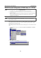
EDS-726 Series User’s Manual 3. 4. EDS Configurator GUI Click on the Upgrade Firmware toolbar icon , or select Upgrade under the Firmware menu. If the switch is Locked, you will be prompted to input the switch’s User Name and Password. Use the Open window to navigate to the folder that contains the firmware upgrade file, and then click on the correct “*.rom” file (eds.rom in the example shown below) to select the file. Click on Open to activate the upgrade process.
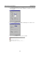
EDS-726 Series User’s Manual EDS Configurator GUI Export Configuration The Export Configuration utility is used to save the entire configuration of a particular EDS-726 to a text file. Take the following steps to export a configuration: 1. Highlight the switch (from the Server list in the Configurator window’s left pane), and then click on the Export toolbar icon or select Export Configuration from the Configuration menu.
EDS-726 Series User’s Manual EDS Configurator GUI Import Configuration The Import Configuration function is used to import an entire configuration from a text file to EDS-726. This utility can be used to transfer the configuration from one EDS-726 to another, by first using the Export Configuration function (described in the previous section) to save a switch configuration to a file, and then using the Import Configuration function. Take the following steps to import a configuration: 1.
EDS-726 Series User’s Manual 4. EDS Configurator GUI Click on Yes in response to the following warning message to accept the new settings. Unlock Server The Unlock Server function is used to open a password protected switch so that the user can modify its configuration, import/export a configuration, etc. There are six possible responses under the Status column.
EDS-726 Series User’s Manual EDS Configurator GUI 2. When the Unlock status window reports Progress as OK, click on the Close button in the upper right corner of the window. 3. The status of the switch will now read either Unlocked or Unlocked Fixed.
A Appendix A MIB Groups MOXA EDS-726 comes with built-in SNMP (Simple Network Management Protocol) agent software that supports cold/warm start trap, line up/down trap, and RFC 1213 MIB-II. The standard MIB groups that MOXA EDS-726 series support are: MIB II.1 – System Group sysORTable MIB II.2 – Interfaces Group ifTable MIB II.4 – IP Group ipAddrTable ipNetToMediaTable IpGroup IpBasicStatsGroup IpStatsGroup MIB II.5 – ICMP Group IcmpGroup IcmpInputStatus IcmpOutputStats MIB II.
EDS-726 Series User’s Manual MIB Groups MIB II.10 – Transmission Group dot3 dot3StatsTable MIB II.11 – SNMP Group SnmpBasicGroup SnmpInputStats SnmpOutputStats MIB II.
EDS-726 Series User’s Manual MIB Groups EDS-726 also provides a private MIB file, located in the file “MOXA-EDS726-MIB.my” on the EDS-726 Series utility CD-ROM. Public Traps: 1. Cold Start 2. Link Up 3. Link Down 4. Authentication Failure 5. dot1dBridge New Root 6. dot1dBridge Topology Changed Private Traps: 1. Configuration Changed 2. Power On 3. Power Off 4. Traffic Overloaded 5. Turbo Ring Topology Changed 6. Turbo Ring Coupling Port Changed 7. Turbo Ring Master Mismatch 8.
B Appendix B Specifications Modular Managed Switch System, EDS-72610G Modular Managed Switch System with 6 slots, and up to 26 ports. PWR1 SPEED FDX/HDX LNK/ACT RING COUPLER PORT PORT PWR2 FAULT STAT MASTER COUPLER CF MODE EtherDevice Switch EDS-726 Technology Standards Protocols MIB Flow Control Interface Fast Ethernet Gigabit Ethernet CompactFlash Interface Console System LED Indicators Module LED Indicators Alarm Contact IEEE802.3, 802.3u, 802.3x, 802.1D, 802.1w, 802.1Q, 802.1p, 802.1X, 802.
EDS-726 Series User’s Manual Digital Inputs Specifications Two inputs with the same ground, but electrically isolated from the electronics. For state “1”: +13 to +30V For state “0”: -30 to +3V Max. input current: 8 mA Power Input Voltage Connection Power Consumption 24 VDC (12 to 45 VDC), redundant dual inputs Two removable 6-pin terminal blocks EDS-72610G 21.5W IM-4TX 2.5W IM-2MSC/2TX 5W IM-2MST/2TX 5W IM-2SSC/2TX 5W IM-4MSC 7.2W IM-4MST 7.2W IM-4SSC 7.2W IM-1LSC/3TX 4W IM-1GTX 2.5W IM-1GSXSC 1.
EDS-726 Series User’s Manual Interface LED Indicators RJ45 Ports Distance Fiber Ports Optical Fiber Distance Multi mode Single mode Min. TX Output 1M-GSX 1M-1GLX 1M-1GLHX 1M-1GZX Max.
EDS-726 Series User’s Manual Specifications IM-2MST/2TX: Interface Module with 2 multi mode 100BaseFX ports, ST connectors, and 2 10/100BaseT(X) ports, RJ45 connectors. IM-2SSC/2TX: Interface Module with 2 single mode 100BaseFX ports, 40 km SC connectors, and 2 10/100BaseT(X) ports, RJ45 connectors. IM-1LSC/3TX: Interface Module with 1 single mode 100BaseFX port, 80 km SC connector and 3 10/100BaseT(X) ports, RJ45 connectors.
EDS-726 Series User’s Manual Mechanical Casing Dimensions Environmental Operating Temperature Storage Temperature Ambient Relative Humidity Regulatory Approvals Safety Hazardous Location EMI EMS Specifications IP30 protection 40 x 130 x 100 mm (W x H x D) 0 to 60°C (32 to 140°F) -40 to 85°C (-40 to 185°F) 5 to 95% (non-condensing) UL60950, UL 508, CSA C22.2 No.
C Appendix C Service Information This appendix shows you how to contact Moxa for information about this and other products, and how to report problems. In this appendix, we cover the following topics.
EDS-726 Series User’s Manual Service Information MOXA Internet Services Customer satisfaction is our number one concern, and to ensure that customers receive the full benefit of our products, Moxa Internet Services has been set up to provide technical support, driver updates, product information, and user’s manual updates. The following services are provided E-mail for technical support................................support@moxanet.com ...............................support@moxa.
EDS-726 Series User’s Manual Service Information Problem Report Form MOXA EDS-726 Series Customer name: Company: Tel: Fax: Email: Date: Serial Number: _________________ Problem Description: Please describe the symptoms of the problem as clearly as possible, including any error messages you see. A clearly written description of the problem will allow us to reproduce the symptoms, and expedite the repair of your product.
EDS-726 Series User’s Manual Service Information Product Return Procedure For product repair, exchange, or refund, the customer must: Provide evidence of original purchase. Obtain a Product Return Agreement (PRA) from the sales representative or dealer. Fill out the Problem Report Form (PRF). Include as much detail as possible for a shorter product repair time. Carefully pack the product in an anti-static package, and send it, pre-paid, to the dealer.