
User's Manual

EDS-726 Series User’s Manual Featured Functions
3-29
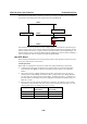
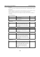
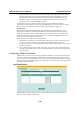
The following figure shows an example of a network that contains VLANs 1 and 2. The VLANs
are connected using the 802.1Q-tagged link between Switch B and Switch C. By default, this link
has a port cost of 100 and is automatically blocked because the other Switch-to-Switch
connections have a port cost of 36 (18+18). This means that both VLANs are now
subdivided—VLAN 1 on Switch units A and B cannot communicate with VLAN 1 on Switch C,
and VLAN 2 on Switch units A and C cannot communicate with VLAN 2 on Switch B.
Block
Switch A
Switch B Switch C
802.1Q tagged,
10BaseTx
half-duplex Link
carries VLAN1, 2
(path cost = 100)
100BaseTX
full-duplex Link;
only carries VLAN2
(path cost = 18)
100BaseTX
full-duplex Link;
only carries VLAN1
(path cost = 18)
EDS-726
EtherDevice Switch
34
IM-4TX
12
PWR
P3
P1
P4
P2
IM-4MST
TX
RX
34
TX
RX
12
PWR
P3
P1
P4
P2
IM-4MSC
TX
RX
3 4
TX
RX
1 2
PWR
P3
P1
P4
P2
IM-2MST/2TX
TX
RX
34
12
PWR
P3
P1
P4
P2
IM-2MSC/2TX
TX
RX
34
12
PWR
P3
P1
P4
P2
IM-1LSC/3TX
4
12
3
TX
RX
PWR
P3
P1
P4
P2
COUPLER CF
STAT
PWR1 FAULT
MASTER
PWR2
IM-1GSXSCIM-1GTX
MODE
RING
PORT
COUPLER
PORT
FDX/HDX
LNK/ACT
SPEED
EDS-726
EtherDevice Switch
34
IM-4TX
12
PWR
P3
P1
P4
P2
IM-4MST
TX
RX
34
TX
RX
1
2
PWR
P3
P1
P4
P2
IM-4MSC
TX
RX
34
TX
RX
12
PWR
P3
P1
P4
P2
IM-2MST/2TX
TX
RX
34
12
PWR
P3
P1
P4
P2
IM-2MSC/2TX
TX
RX
34
12
PWR
P3
P1
P4
P2
IM-1LSC/3TX
4
12
3
TX
RX
PWR
P3
P1
P4
P2
COUPLER CF
STAT
PWR1 FAULT
MASTER
PWR2
IM-1GSXSCIM-1GTX
MODE
RING
PORT
COUPLER
PORT
FDX/HDX
LNK/ACT
SPEED
To avoid subdividing VLANs, all inter-switch connections should be made members of all
available 802.1Q VLANs. This will ensure connectivity at all times. For example, the connections
between Switches A and B, and between Switches A and C should be 802.1Q tagged and carrying
VLANs 1 and 2 to ensure connectivity.
See the “Configuring Virtual LANs” section for more information about VLAN Tagging.
Configuring STP/RSTP
The following figures indicate which Spanning Tree Protocol parameters can be configured. A
more detailed explanation of each parameter is given below the figure.
At the top of this page, the user can check the “Current Status” of this function. For RSTP, you
will see: