MOXA VPort 2310 Video Server User’s Manual First Edition, January 2005 Moxa Networking Co., Ltd. Tel: +886-2-2910-1230 Fax: +886-2-2910-1231 Web: www.moxa.com MOXA Technical Support Worldwide: support@moxanet.com The Americas support@moxa.
VPort 2310 User’s Manual The software described in this manual is furnished under a license agreement and may be used only in accordance with the terms of that agreement. Copyright Notice Copyright 2005 Moxa Neworking Co., Ltd. All rights reserved. Reproduction without permission is prohibited. Trademarks MOXA is a registered trademark of the Moxa Group. All other trademarks or registered marks in this manual belong to their respective manufacturers.
Before getting started Before using your VPort 2310, please pay close attention to the following items: ! After opening the VPort 2310 box, compare the contents of the box with the Package Checklist in Chapter 1. Notify your sales representative if any of the items is missing or damaged. ! To prevent damage or problems caused by improper usage, before assembling and operating the device and peripherals, read the Quick Installation Guide (the printed handbook included in the package).
Table of Contents Chapter 1 Introduction ..................................................................................................1-1 Overview.................................................................................................................................. 1-2 Package Checklist .................................................................................................................... 1-3 Product Features .....................................................................
Factory default............................................................................................................ 4-23 System Configuration Via FTP .............................................................................................. 4-23 CONFIG.INI............................................................................................................... 4-23 System Configuration Via Telnet ...........................................................................................
Video configuration URL ....................................................................................................... A-4 Image quality configuration URL ........................................................................................... A-5 Camera configuration URL..................................................................................................... A-5 Camera preset configuration URL ..........................................................................................
1 Chapter 1 Introduction VPort 2310 is a high-performance networking video server. In addition to meeting the basic needs of video feed, many advanced features are included to help you set up surveillance or web attraction applications. VPort 2310 is designed to provide stability, robustness, ease-of-use, and flexibility.
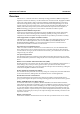
VPort 2310 User’s Manual Introduction Overview VPort 2310 is a 1-channel Video Server that adopts the high performance MPEG4 compression algorithm to enhance the efficiency of video transmission via the IP network. Equipped with BNC video input, image digitizer, image compressor (DSP) and 10/100 Mbps Ethernet connectivity, VPort 2310 can digitize any analog video source and distribute these digital images over an IP network, turning your CCTV system into a “Video over IP” Network System INSTANTLY.
VPort 2310 User’s Manual Introduction with a free upgrade wizard included to facilitate firmware installation. Technical support for developers The high-performance Video Server can be integrated into many applications—without busting your budget—and the complete programming interface of MOXA ActiveX Control SDK makes the developer’s job easy and straightforward. More ideas for Video Server applications can be found on our website.
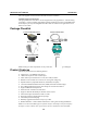
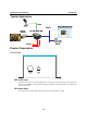
VPort 2310 User’s Manual Introduction Typical Application Audio http://192.168.4.100 TCP/IP Analog Camera IP: 192.168.4.100 Server DI/ DO Product Description Front Panel VIDEO IN AUDIO IN BNC video input The BNC video input is a 75 Ohm video port for connecting an external camera. To ensure that the correct video modulation type is detected, cameras should be connected and powered on before the VPort is powered on.
VPort 2310 User’s Manual Introduction Rear Panel 1 INPUT 12 VDC COM RS-485 Relay Output NO 2 Digtal Input C: Common NO: Normal Open C 3 RESET 1: NETWORK 2: CONNECT 3: SERIAL 10/100 Mbps Ethernet COM (RS-232) Network and Status LEDs Each time the Video Server starts up, it performs a Power-On-Self-Test (POST) to examine each hardware module. VPort 2310 Video Server has 3 LEDs: 1. NETWORK: detects the network’s Tx/Rx status 2. CONNECT: checks if the Video Server alive or not 3.
VPort 2310 User’s Manual Introduction General I/O terminal block COM RS-485 Relay Output Digital Input + NO C + Data+ DataNormal Open Max. 1A, 24 VDC or 0.5A, 125 VAC COMMON Short with Normal Close at the initial state DIDI+ Max. 50 mA, 12 VDC The Video Server provides a very flexible general I/O interface that can be used with security devices, such as sensors, alarms, lighting fixtures, or door locks. The general I/O terminal block has six pins for device control.
VPort 2310 User’s Manual Introduction Reset Button A recessed RESET button is provided for restoring the system to the factory default settings. When the system fails to install properly, or operates abnormally, use the wrench included in the package to reset the system back to its original status. The procedure is as follows: Step 1: Insert the wrench into the hole to press down on the reset button, which is located about 1.5 cm inside the surface of the casing.
2 Chapter 2 Getting Started This chapter includes information about how to install a VPort 2310 Video Server.
VPort 2310 User’s Manual Getting Started Before Getting Started In what follows, “user” refers to those who can access the Video Server, and “administrator” refers to the person who knows the root password that allows changes to the Video Server’s configuration, in addition to providing general access. Administrators should read this part of the manual carefully, especially during installation.
VPort 2310 User’s Manual NOTE Getting Started After powering on the VPort 2310, wait a few seconds for the POST (Power On Self Test) to run. The IP address will be assigned when the CONNECT LED is lit. Using IP Reporter NOTE 1. Run IPReporter.exe to search for the VPort. After the IP Reporter window opens, you may also click on the Search button to initiate a search. 2. When the search has concluded, the MAC address and IP address of the VPort will be listed in the IP Reporter window.
VPort 2310 User’s Manual 3. Getting Started Click on the VPort whose MAC address matches the one you just installed, and then click on Link to the selected device to access the VPort via your web browser. You will be able to modify VPort’s IP address and other settings when the VPort’s homepage opens. Non-DHCP Server Environment If your VPort 2310 is connected to a network that does not have a DHCP server, then you will need to configure the IP address manually.
VPort 2310 User’s Manual Getting Started Assigning the IP Address Manually To change the IP address of VPort manually, access VPort’s web server, and then navigate to the Configuration # Network page to configure the IP address and other network settings. Uncheck the Reset IP address at next boot to ensure that the IP address you assign is not deleted each time the VPort is restarted.
3 Chapter 3 Accessing VPort 2310 for the First Time This chapter includes information about how to access VPort 2310 Video Server for the first time.
VPort 2310 User’s Manual Accessing VPort 2310 Video Server for the First Time Accessing VPort 2310 Opening Your Browser Open your browser, type the VPort’s IP address in the Address box, and then press Enter. Authentication After opening your browser and typing the VPort’s IP address, you will be requested to enter the User name and the Password. When accessing the VPort for the first time, administrators must enter root as the username, and the MAC address, in capital letters, as the password.
VPort 2310 User’s Manual NOTE Accessing VPort 2310 Video Server for the First Time The MAC address is located on the VPort 2310’s back panel. It is also shown in the IP Reporter window after the VPort has been located. Installing the Plug-in Application If you access the VPort for the first time via a browser that supports server push (e.g., Netscape), the video images will be displayed directly.
VPort 2310 User’s Manual Accessing VPort 2310 Video Server for the First Time Functions Featured on VPort’s Homepage PTZ Camera Control Custom PTZ Camera Commands Logo and Host Name The default logo is Moxa’s logo, and the host name is VPort 2310 Video Server. For customized usage, the administrator can change the layout of the homepage from the Homepage Layout page. Camera Image View The assigned caption and system date/time will be displayed in the banner above the image window.
VPort 2310 User’s Manual Accessing VPort 2310 Video Server for the First Time Relay Output Control VPort 2310 Video Server has 1 DI/DO for external devices, such as sensors and alarms. If external devices are attached to the digital output, administrators or permitted users can click on Open to short the Common and Normal Open pins of the digital output, or click on Close to short the Common and Normal Close pins of the digital output.
VPort 2310 User’s Manual Accessing VPort 2310 Video Server for the First Time selected protocol will be recorded in the user's PC and will be used for the next connection. If the network environment is changed, or you want to refresh the web browser, manually select the UDP protocol, save, and then return HOME to re-connect.
4 Chapter 4 System Configuration After installing the hardware, the next task required is to configure VPort 2310’s settings.You may use one of three configuration methods: via web access, via FTP, and via Telnet.
VPort 2310 User’s Manual System Configuration System Configuration Via Web Access System configuration can be done remotely with Internet Explorer via the Web Server. Alternatively, administrators may type the system configuration URL, “http:///setup/config.html”, to enter the configuration page directly. Administrators who wish to set up certain options by using the URL should refer to the relevant section in Chapter 6, “URL Commands,” for advanced functions.
VPort 2310 User’s Manual System Configuration Date and Time The default setting for Date and Time is Keep current date and time. You may also choose from one of the following date and time configuration options: 1. The easiest way to adjust the date and time is to make the VPort Sync with computer time. 2. Select the Manual option if you wish to set the date and time manually by entering new settings. 3.
VPort 2310 User’s Manual System Configuration Security Root password To change the administrator’s password, type the new password in both the Root password box and Confirm password box. The passwords you enter will be displayed in asterisks for security reasons. The maximum string length for a password is 14 characters. After clicking on Save to validate the new password, a window will open to ask the administrator for the new password to access the VPort.
VPort 2310 User’s Manual System Configuration select control camera or control DO options for the demo account. Separating the demo account from the primary users can prevent interference with normal operations. Network Reset network at next boot 1. $ Reset network at next boot In this case, the installation process will be run again when the system reboots (i.e., when you save system configuration or re-power on the VPort).
VPort 2310 User’s Manual NOTE System Configuration VPort’s Network and Status LEDs can be used to determine if the VPort is transmitting and receiving data over the network. Refer to Chapter 1 to see how to interpret the Network and Status LEDs. General Administrators may need to modify the network settings to connect to an existing network since the subnet mask for some broadband services may differ from the default value of 255.255.255.
VPort 2310 User’s Manual System Configuration NOTE Whenever the system reboots, a system log will be sent out via email or FTP to show the login status of VPort. The system log will be sent to the Sender email address if the SMTP server settings are correct. To send the system log via FTP, the SMTP server should be erased since the E-mail system is used by default to transmit the system log. NOTE In either e-mail or FTP, the 1st server information should be entered first.
VPort 2310 User’s Manual NOTE System Configuration If you make any changes to the settings on this web page, the system will restart to validate those changes. Make sure that every field is correctly typed before clicking on Save. If the VPort fails to respond due to incorrect settings, perform the installation procedures again (as described in the beginning of Chapter 2). DDNS & UPnP Two tools are available for administrators to link conveniently to VPort 2310.
VPort 2310 User’s Manual System Configuration Step 3: Key in the Host Name you applied for linking to VPort. Step 4: Key in the Username/E-mail and Password/Key to enable the service from the DDNS service provider (based on the rules of DDNS websites). Step 5: Click save to enable the DDNS configuration of VPort Universal PnP Checkmark the □ Enable UPnP box, and click save to enable the UPnP function. Users will be able to find and connect to the VPort directly from the operating system’s network device.
VPort 2310 User’s Manual System Configuration Size There are 5 options for selecting image sizes: Video Size (unit: pixels) Half Half × 2 Standard Standard × 2 Double NOTE NTSC 176 × 352 × 352 × 704 × 704 × 112 240 240 480 480 PAL 176 × 352 × 352 × 704 × 704 × 112 288 288 576 576 Half × 2 consumes the same file size and bandwidth as Half, but has the same resolution as Standard. For this reason, the visual effect of Half × 2 is worse than Standard.
VPort 2310 User’s Manual NOTE System Configuration The default video quality control setting is Fixed bit rate at 384 Kbps. At this bandwidth, the image quality is good under most conditions if the FPS is near 30 and the video size is normal.
VPort 2310 User’s Manual System Configuration run the installation process again to relocate the VPort’s IP address. Motion Detection Three areas can be selected for configuring VPort 2310’s VMD (video motion detection) function. The VMD alarm will only be triggered when the VMD conditions in these 3 specific areas are met. Each area can be fine tuned to fit the environment for different VMD conditions by setting Sensitivity and image change Percentage. 1.
VPort 2310 User’s Manual System Configuration that it fits the desired VMD area. Step 3: Use Window Name to assign a name to this VMD window (refer to the Trigger Condition in the Configuration/Application page). Step 4: Set up the Sensitivity and Percentage parameters by moving the percentage cursor. Step 5: Click on the Save button to save the settings. Step 6: To test the VMD condition, check the action of the graphics bar on the left side of the save button.
VPort 2310 User’s Manual System Configuration Application Undefined NOTE After you set up the motion detection window, the Window name will be changed from “Undefined” to the name you assigned it. VPort 2310 Video Server provides 3 major applications. 1. Weekly schedule: Administrators can set up the Application schedule by weekly day and time. 2.
VPort 2310 User’s Manual System Configuration Step 1: ○All the time except for the above schedule Choose the operation period ○Weekly schedule □Sun □Mon snapshot begin snapshot end Step 2: □Tue □Wed □Thu 00:00:00 00:00:00 □Fri □Sat [hh:mm:ss] [hh:mm:ss] □ Event operation □ Sequential mode Step 3: Step 3-1: setup the General Snapshot every □ seconds Set up the application’s actions Delay □ seconds before detecting the next event Take snapshot at □ seconds after event Choose the application
VPort 2310 User’s Manual System Configuration Weekly schedule The Weekly schedule is provided for daily security applications. Administrators can select any weekday from Monday to Friday with the daily schedule set from 9 am to 6 pm when no one is available to perform event checking. If the security system is installed in an office for which no one is present on nights or weekends, administrators can still set the time period as above, from 9 am to 6 pm.
VPort 2310 User’s Manual a. System Configuration Trigger output alarm. Administrators can set the trigger output alarm when the DI or Video Motion Detection conditions are met. Check the box of the listed action to enable the triggered output alarm. b. NOTE Upload snapshot. Administrators can set the upload snapshot action when the DI or Video Motion Detection conditions are met. VPort 2310 Video Server will take 3 JPEG snapshot images: VPRE.JPG (pre-event), VTRG.JPG (the moment of event) and VPOS.
VPort 2310 User’s Manual System Configuration Interface mode The COM port supports 2 serial interfaces, although only one interface can be used at a time. Depending on the interface used by the attached device, administrators must set the Interface mode to either RS-232 or RS-485. NOTE The RS-232 interface is used via the DB9 COM port, and RS-485 interface is used via the GPIO. These 2 interfaces cannot be used at the same time.
VPort 2310 User’s Manual System Configuration Custom commands VPort 2310 Video Server provides 5 custom commands in addition to the general pan, tilt, zoom, and preset functions. Administrators can click on Custom Command to configure, and refer to the manual enclosed with the attached PTZ camera to set up frequently-used functions. The Command should be entered in ASCII format. The VPort will translate the commands into binary code and send them out through the serial port.
VPort 2310 User’s Manual System Configuration Custom Camera Settings If the PTZ camera’s driver is not in the list, the administrator can select the custom camera from the Select Camera driver menu to program the PTZ camera with ASCII code. A custom camera window will pop up when the Setting for Custom Camera button is clicked. Input the ASCII code into this window.
VPort 2310 User’s Manual System Configuration Homepage Layout VPort 2310 Video Server allows administrators to customize the layout of the Video Server’s homepage. Logo figure 1. Select the blank option to hide the logo that appears in the upper-left corner of the homepage. 2. The “default” logo is the MOXA logo. 3. An external logo or image can be used by selecting the URL option, and typing the url for the image in the text input box.
VPort 2310 User’s Manual System Configuration View log file The system log contains useful information, including current system configuration and activity history with timestamp for tracking. View parameters Clicking on “View parameters” allows you to view all system parameters, which are listed by category. The content is the same as VPort 2310 Video Server’s CONFIG.INI file.
VPort 2310 User’s Manual System Configuration Factory default This function is used to restore the Video Server to its factory default settings, so that any changes that were made previously will be lost. After clicking OK, the system will restart. Note that it will take some time for the restore action to finish. You will need to run the software installation program to set up the network. System Configuration Via FTP CONFIG.
VPort 2310 User’s Manual System Configuration of the field, and the bold italic characters are the options for the field.
VPort 2310 User’s Manual System Configuration (10) (11) (12) (13) (14) (15) (16) (17) (18) (19) (20) (21) en 0 0 Current Language, read-only read-only 0-Hourly, 1-daily, 2-weekly, 3-monthly [LAYOUT] 1 0 1 1 http:// http:// http:// 0-black, 1-white, 2-green, 3-maroon, 4olive, 5-navy, 6-purple, 7-gray, 8-yellow, 9-lime, 10-aqua, 11-fuchsia, 12-silver, 1
VPort 2310 User’s Manual System Configuration 255.255.255.0 0.0.0.0 0.0.0.0 0.0.0.
VPort 2310 User’s Manual System Configuration string with maximum of 14 characters string with maximum of 40 characters NO 80 5001
VPort 2310 User’s Manual System Configuration 0 0 0 0 YES 384K between 5 and –5 between 5 and –5 between 5 and –5 between 5 and –5 or NO values:64k, 128k, 256k, 384k, 512k, 768k, 1000k, 1200k 30
VPort 2310 User’s Manual System Configuration string with maximum of 60 characters DOWN string with maximum of 60 characters LEFT string with maximum of 60 characters RIGHT string with maximum of 60 characters TELESCOPE string with maximum of 60 characters WIDE string with maximum of 60 characters NEAR string with maximum of 60 characters FAR string with maximum of 60 characters [ALERT] 0 disabled, 1 for Sequential, 10 for motion detection event, 12 for DI event 0
VPort 2310 User’s Manual System Configuration status is not recorded. Administrators can type the “debug” command to examine in-depth core debugging information. This causes Video Server to start dumping the detailed debugging information while the system is running. This is useful for examining if any errors have occurred when the system operates abnormally. The stored information will be cleared automatically after the dump.
5 Chapter 5 Advanced Applications This chapter will introduce more advanced applications.
VPort 2310 User’s Manual Advanced Applications Capturing Up-to-date Still Images Getting snapshot via URL Administrators and users can use a specific URL to capture the current still image. URL http:///cgi-bin/video.jpg Getting snapshot via FTP Administrators and users can log in to the Video Server FTP daemon to download the refreshed JPEG image named video.jpg. The user name and password are the same as for web access.
VPort 2310 User’s Manual Advanced Applications Download Event-triggered Snapshots There are three video image files for the video channel of three stages: pre-alarm, the moment when triggered, and post-alarm. Only the snapshots captured by the last event are preserved. Administrator and users can use FTP or URL to get the saved snapshots. They can also be browsed from the application page under system configuration. Getting triggered snapshots via URL /cgi-bin/snapshot.
VPort 2310 User’s Manual Advanced Applications URL Commands for DI/DO & Camera’s Actions Setting Query status of digital inputs /setup/getdi.cgi Video Server will return status of four digital inputs in one line. Drive digital outputs /setup/setdo.cgi?do= Where state is H, L. H means NC connected with COMMON and L means NO connected with COMMON. For example, http://192.168.0.201/setup/setdo.cgi?do=h will command the Video Server, with IP address of 192.168.0.
VPort 2310 User’s Manual Advanced Applications Sending commands to devices attached to the COM port This URL applies to the attached serial port device including supported PTZ cameras or non-supported custom camera. Note that the serial port settings of custom cameras must be correctly defined in advance. /cgi-bin/senddata.
6 Chapter 6 Upgrading System Firmware Customers can check the appropriate product page on Moxa’s website to download the latest firmware. Only administrators can upgrade the system firmware of Video Server.
VPort 2310 User’s Manual Upgrading System Firmware Using Upgrade Wizard to Upgrade Firmware Step 1: Run the Upgrade Wizard (.exe) included in the product CD Step 2: Type the web address of the Video Server whose firmware you want to upgrade, and then type the administrator password. Click on Next to proceed. Step 3: The program will detect the Video Server. If the password is incorrect, a window will appear asking you to recheck the FTP port and password.
VPort 2310 User’s Manual NOTE Upgrading System Firmware The power supply of VPort 2310 Video Server should not be turned off when the Upgrade Wizard is upgrading the firmware. Otherwise, the firmware upgrade will fail, and you will need to return the video server to Moxa for repair. Using FTP to Upgrade Firmware Step 1: Use the FTP program and change the working directory to the local folder where FLASH.BIN resides. Step 2: Connect to Video Server with user name “root” and password.
7 Chapter 7 Troubleshooting This chapter describes some problems that might occur during installation or operation, and provides the basic solutions to those problems.
VPort 2310 User’s Manual Troubleshooting Power On Self Test (POST) After the power has been turned on, Video Server will perform a self-diagnostic to detect any possible hardware defects. The status LEDs will blink during the POST, and will keep blinking until the POST has finished, or a fatal error is detected. If either status LED indicator is dim to start off with, the LED may be broken.
VPort 2310 User’s Manual Troubleshooting Q: What is the plug-in for? A: The plug-in provided by Video Server is used to display motion pictures on versions of Internet Explorer that do not support server push technology. If your system does not allow installation of any plug-in software, the security level of the web browser may need to be lowered. It is recommended that you consult the network supervisor in your office before adjusting the security level.
VPort 2310 User’s Manual Troubleshooting Q: How can I keep the Video Server as private as possible? A: The Video Server is designed for surveillance purposes and has many flexible interfaces. The user authentication and special confirmation in installation can keep the Video Server from unauthorized access. You may also change the HTTP port to a non-public number. You can check the system log to examine any abnormal activities and trace the origins. Q: I have a PTZ camera that is not on the support list.
A Appendix A URL Commands of Video Server Video Server can be easily integrated with existing websites or web control applications using convenient URLs. This section lists the commands in URL format corresponding to the basic functions of Video Server. Some RFC standards related to HTML may be a good reference for implementation of the customized homepage. Page URL The configuration page has a frame layout that includes an option list frame and an option page frame.
VPort 2310 User’s Manual URL Commands of Video Server System Resource URL Some images are used on the homepage when the homepage layout is in image mode. Administrators may use the following links to show the images saved on Video Server on another page. To change the logo or the background images referenced by the URL, refer to the homepage layout section under configuration. Resource name Reference URL system logo image /pic/logo.gif background image /pic /back.
VPort 2310 User’s Manual URL Commands of Video Server Network configuration URL URL: /setup/network.
VPort 2310 User’s Manual URL Commands of Video Server Video configuration URL URL: /setup/video.
VPort 2310 User’s Manual URL Commands of Video Server Image quality configuration URL URL: /setup/image.
VPort 2310 User’s Manual URL Commands of Video Server Custom camera configuration URL URL: /setup/custom.
VPort 2310 User’s Manual URL Commands of Video Server Homepage layout configuration URL URL: Name cuslogo logourl linkurl cusback backurl fcolor bcolor /setup/layout.
B Appendix B Settings of Supported PTZ Cameras Since the COM port settings can be adjusted to other than the default settings, check the correct default settings for the attached camera.
C Appendix C Camera Control Cable The included cable can be used to control motorized cameras of desktop types from Sony and Canon. The pin assignment is illustrated in the following chart. To control cameras of another brand, check the user’s manual of the motorized camera to see if the pin assignment of the control cable is appropriate.
D Appendix D Time Zone Table The hour offsets for different time zones are shown below. You will need this information when setting the time zone in automatic date/time synchronization. GMT stands for Greenwich Mean Time, which is the global time that all time zones are measured from.
VPort 2310 User’s Manual (GMT+02:00) (GMT+02:00) (GMT+02:00) (GMT+03:00) (GMT+03:00) (GMT+03:00) (GMT+03:00) (GMT+03:30) (GMT+04:00) (GMT+04:00) (GMT+04:30) (GMT+05:00) (GMT+05:00) (GMT+05:30) (GMT+05:45) (GMT+06:00) (GMT+06:00) (GMT+06:00) (GMT+06:30) (GMT+07:00) (GMT+07:00) (GMT+08:00) (GMT+08:00) (GMT+08:00) (GMT+08:00) (GMT+08:00) (GMT+09:00) (GMT+09:00) (GMT+09:00) (GMT+09:30) (GMT+09:30) (GMT+10:00) (GMT+10:00) (GMT+10:00) (GMT+10:00) (GMT+10:00) (GMT+11:00) (GMT+12:00) (GMT+12:00) (GMT+13:00) Time Z
E Appendix E Technology Video Inputs (BNC) Audio Inputs (RCA) NTSC/PAL Network Protocols Ethernet Video Video Compression Video Resolution Video Viewing Serial Port COM RS-485 GPIO Digital Input Relay Output LED Indicators Technical Specifications 1 1 mono (24 Kbps wideband audio coding) Auto-sensing TCP, UDP, HTTP, SMTP, FTP, Telnet, NTP, DNS, DDNS, DHCP, UPnP Auto-sensing 10/100 Mbps MPEG4 NTSC: Up to 30 frames at 176 × 120 Up to 30 frames at 352 × 240 Up to 10 fames at 704 × 480 PAL: Up to 25 fr
VPort 2310 User’s Manual Technical Specifications Mechanical Dimensions (W x D x H ) Weight Installation 72.25 x 106 x 50 mm 420 g DIN-Rail Mounting, Wall Mounting Power Requirements Input Consumption 6-15 VDC min.15W near 4.
F Appendix F Service Information This appendix shows you how to contact Moxa for information about this and other products, and how to report problems. In this appendix, we cover the following topics.
VPort 2310 User’s Manual Service Information MOXA Internet Services Customer satisfaction is our number one concern, and to ensure that customers receive the full benefit of our products, Moxa Internet Services has been set up to provide technical support, driver updates, product information, and user’s manual updates. The following services are provided E-mail for technical support................................support@moxanet.com World Wide Web (WWW) Site for product information: .....................
VPort 2310 User’s Manual Service Information Problem Report Form MOXA VPort 2310 Customer name: Company: Tel: Fax: Email: Date: 1. Moxa Product: & VPort 2310 2. Serial Number: _________________ Problem Description: Please describe the symptoms of the problem as clearly as possible, including any error messages you see. A clearly written description of the problem will allow us to reproduce the symptoms, and expedite the repair of your product.
VPort 2310 User’s Manual Service Information Product Return Procedure For product repair, exchange, or refund, the customer must: ' Provide evidence of original purchase. ' Obtain a Product Return Agreement (PRA) from the sales representative or dealer. ' Fill out the Problem Report Form (PRF). Include as much detail as possible for a shorter product repair time. ' Carefully pack the product in an anti-static package, and send it, pre-paid, to the dealer.