EM-1220 LX User’s Manual Fourth Edition, January 2010 www.moxa.com/product © 2010 Moxa Inc. All rights reserved. Reproduction without permission is prohibited.
EM-1220 LX User’s Manual The software described in this manual is furnished under a license agreement and may be used only in accordance with the terms of that agreement. Copyright Notice Copyright © 2010 Moxa Inc. All rights reserved. Reproduction without permission is prohibited. Trademarks MOXA is a registered trademark of Moxa Inc. All other trademarks or registered marks in this manual belong to their respective manufacturers.
Table of Contents Chapter 1 Introduction ..................................................................................................1-1 Overview.................................................................................................................................. 1-2 Ordering Information ............................................................................................................... 1-2 Product Specifications .................................................................
Configuring Dial-in/Dial-out Service ...................................................................................... 4-8 Dial-out Service............................................................................................................ 4-8 Dial-in Service.............................................................................................................. 4-8 Configuring PPPoE............................................................................................................
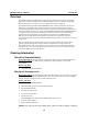
1 Chapter 1 Introduction The Moxa EM-1220-LX is a mini RISC-based ready-to-run embedded module that features dual 10/100 Mbps Ethernet ports and two RS-232/422/485 serial ports in a µClinux ARM9 module. In addition, the EM-1220-LX supports an external SD socket for installing an SD memory card for storage expansion, and offers high performance communication and unlimited storage in a super compact, palm-sized module.
EM-1220 LX User’s Manual Introduction Overview The EM-1220-LX is a mini RISC-based communication platform that is ideal for embedded applications. The EM-1220-LX supports 2 RS-232/422/485 serial ports and dual 10/100 Mbps Ethernet LAN ports to provide users with a versatile communication platform. The EM-1220-LX uses the Moxa ART ARM9 RISC CPU.
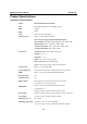
EM-1220 LX User’s Manual Introduction Product Specifications Hardware Specifications Model EM-1220-LX Embedded Module CPU MOXA ART ARM9 32-bit 192 MHz processor RAM 16 MB Flash 8 MB LAN Auto-sensing 10/100 Mbps × 2 LAN Protection Built-in 1.
EM-1220 LX User’s Manual Storage temperature Introduction -20 to 80°C (-4 to 176°F), 5 to 95% RH -40 to 85°C (-40 to 185°F) is optional for EM-1220-T model Module Interface Two 2 × 17 pin-headers; pitch: 2.5 × 2.5 mm Software Specifications Kernel µClinux Kernel 2.6.
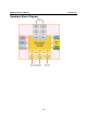
EM-1220 LX User’s Manual Introduction Hardware Block Diagram 1-5
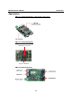
EM-1220 LX User’s Manual Introduction Appearance EM-1220-LX Embedded Module + EM-1220-DK Carrier Board EM-1220-LX Embedded Module MOXA ART ARM9 32-bit Communication Processor onboard 16 MB RAM EM-1220-LX Development Kit 1-6
EM-1220 LX User’s Manual Introduction Dimensions EM-1220-LX Embedded Module 80cm 50cm EM-1220-DK Carrier Board Installing the EM-1220-LX To use the EM-1220-LX Development Kit, insert the EM-1220-LX embedded module vertically onto the development kit. Note that the pin marked “J2” on the embedded module must be matched with the pin marked “J2” on the development kit; and the pin marked “J1” on the embedded module must be matched with the pin marked “J1” on the development kit.
EM-1220 LX User’s Manual Introduction Wiring Requirements This section describes how to connect the EM-1220-LX to serial devices. Be sure to heed the following common safety precautions before proceeding with the installation of any electronic device: y Use separate paths to route wiring for power and devices. If power wiring and device wiring paths must cross, make sure the wires are perpendicular at the intersection point.
EM-1220 LX User’s Manual Introduction ATTENTION This product should be mounted to a well-grounded mounting surface such as a metal panel. SG SG: The Shielded Ground (sometimes called Protected Ground) contact is the left most contact of the 3-pin power terminal block connector when viewed from the angle shown here. Connect the SG wire to an appropriate grounded metal surface.
EM-1220 LX User’s Manual Introduction Connecting to a Serial Device Connect the serial cable between the EM-1220-DK and the serial device(s). Serial ports P1 and P2 on EM-1220-DK use male DB9 connectors, and can be configured for RS-232, RS-422, or RS-485 by software.
EM-1220 LX User’s Manual Introduction Additional Functions Reset Button Press the Reset button on the EM-1220-DK continuously for at least 5 seconds to load the factory default configuration. After the factory default configuration has been loaded, the system will reboot automatically. We recommend that you only use this function if the software is not working properly and you want to load factory default settings.
2 Chapter 2 Getting Started In this chapter, we explain the basic procedure for getting the EM-1220-LX connected and ready for use. In this chapter we cover the following topics: Powering on the EM-1220-DK Connecting the EM-1220-LX to a PC ¾ Console Port ¾ Telnet Configuring the Ethernet Interface Installing a Secure Digital (SD) Memory Card Developing Your Applications ¾ Installing the EM-1220-LX Tool Chain ¾ Compiling Hello.
EM-1220 LX User’s Manual Getting Started Powering on the EM-1220-DK Connect the SG wire to the Shielded Contact located on the upper left corner of the EM-1220-DK, and then power on the EM-1220-DK by connecting the power adaptor. It takes about 16 seconds for the system to boot up. Once the system is ready, the Ready LED will light up. ATTENTION After connecting the EM-1220-DK to the power supply, it will take about 16 seconds for the operating system to boot up.
EM-1220 LX User’s Manual Getting Started Telnet If you know at least one of the two IP addresses and netmasks, then you can use Telnet to connect to the EM-1220-LX’s console. Default IP Address Default Netmask LAN 1 192.168.3.127 255.255.255.0 LAN 2 192.168.4.127 255.255.255.0 Telnet can be used locally by using a crossover Ethernet cable to connect your computer to the EM-1220-LX, or over a LAN or the Internet. The default IP addresses and netmasks are shown above.
EM-1220 LX User’s Manual Getting Started Configuring the Ethernet Interface In this section, we use the serial console to explain how to modify the EM-1220-LX’s network settings. 1. Change directories by issuing the command cd /etc. Type the command vi rc to use VI Editor to edit the configuration file. The IP addresses for the EM-1220-LX’s LAN1 and LAN2 are: ifconfig eth0 192.168.3.127 ifconfig eth1 192.168.4.127 as shown in the following figure. Edit these two lines to modify the static IP addresses.
EM-1220 LX User’s Manual 2. Getting Started You may also configure the EM-1220-LX to request IP addresses from a DHCP server. In this case, use the sharp sign (#) to comment out one or both “ifconfig” lines, and then add the setting about the “dhcpcd” into the rc file as below. dhcpcd -p -a eth0 & dhcpcd -p -a eth1 & Note that the EM-1220-LX will send out DHCP broadcast packets, and then get the IP addresses from the first DHCP server that responds. 3.
EM-1220 LX User’s Manual Getting Started Installing a Secure Digital (SD) Memory Card The EM-1220 Development Kit has an internal SD socket for storage expansion. To access this socket, perform the following steps to install the SD memory card. Step 1: Locate the SD socket. Step 2: Insert the SD card into the socket. Make sure the card is situated correctly. Step 3: Push the SD card inward.
EM-1220 LX User’s Manual Getting Started Developing Your Applications Step 1: Connect the EM-1220-DK to a Linux PC. Step 2: Install Tool Chain (GNU Cross Compiler & uClibc). Step 3: Configure cross compiler and uClibc environment variables. Step 4: Code & compile your program. Step 5: Download program to the EM-1220-LX by FTP or NFS. Step 6: Debug the program. If the program is OK, proceed to Step 7. If the program needs to be modified, go back to Step 4.
EM-1220 LX User’s Manual Getting Started Compiling Hello.c The Tool Chain path is: PATH=/usr/local/bin:$PATH The EM-1220-LX CD includes several example programs. We use Hello.c to illustrate how to compile and run applications. Issue the following commands from your PC to compile Hello.c: # cd /tmp/ # mkdir example # cp –r /mnt/cdrom/example/* /tmp/example Go to the Hello subdirectory, and then issue the command #make to compile Hello.c. Finally, execute the program to generate hello and hello.gdb.
EM-1220 LX User’s Manual Getting Started Uploading “Hello” to the EM-1220-LX To use FTP to upload hello to the EM-1220-LX, issue the following commands from the PC: #ftp 192.168.3.127 ftp> cd /home ftp> bin ftp> put ./hello ftp> quit #telnet 192.168.3.
EM-1220 LX User’s Manual Getting Started Running “Hello” on the EM-1220-LX To run the Hello program, issue the following commands on the EM-1220-LX: # chmod 755 hello #./hello The words “hello world” are printed on the screen. ATTENTION Be sure to calculate the amount of Flash Memory used by the User File System in the Flash ROM.
EM-1220 LX User’s Manual Getting Started Make File Sample Code The following Make File example code was copied from the Hello example on the EM-1220-LX’s CD-ROM. srcdir = . LDFLAGS = -Wl,-elf2flt LIBS = CFLAGS = # Change these if necessary CC = arm-elf-gcc CPP = arm-elf-gcc -E all: hello hello: $(CC) -o $@ $(CFLAGS) $(LDFLAGS) $(LIBS) $@.c clean: rm -f $(OBJS) hello core *.
3 Chapter 3 Software Package This chapter includes information about the software used with the EM-1220-LX.
EM-1220 LX User’s Manual Software Package EM-1220-LX Software Architecture The pre-installed µClinux operating system used by the EM-1220-LX follows the standard µClinux architecture. This means that programs following the POSIX standard are easily ported to the EM-1220-LX with the GNU Tool Chain provided by www.uClinux.org. In addition to the Standard POSIX API, device drivers for the buzzer and UART for the serial ports are also included.
EM-1220 LX User’s Manual Software Package The partition sizes are hard coded into the kernel binary. You must rebuild the kernel to change the partition sizes. The flash memory map is shown in the following table.
EM-1220 LX User’s Manual Software Package EM-1220-LX Software Package Bin upkernel passwd -> tinylogin login -> tinylogin tinylogin telnetd snmpd mail sh routed netstat arp chat pppd portmap ntpdate necid eraseall kversion init expand inetd hwclock ftpd ftp mke2fs e2fsck discard dhcpcd cpu busybox boa downramdisk upramdisk dev mtdblock1 mtdr1 mtd1 mtdblock0 mtdr0 mtd0 cum1 cum0 ttyM1 ttyM0 urandom random zero ttypf ttype ttypd ttypc ttypb ttypa ttyp9 ttyp8 ttyp7 ttyp6 ttyp5 ttyp4 ttyp3 ttyp2 ttyp1 ttyp0
EM-1220 LX User’s Manual Software Package Bin dev ptyp0 ppp pio rtc ram1 ram0 null kmem mem cua0 console tty 3-5
4 Chapter 4 Configuring the EM-1220-LX In this chapter, we describe how to configure the EM-1220-LX Series products.
EM-1220 LX User’s Manual Configuring the EM-1220-LX Enabling and Disabling Daemons The following daemons are enabled when the EM-1220-LX boots up for the first time. y y y y y SNMP Agent daemon: Telnet Server / Client daemon: Internet Daemons: FTP Server / Client daemon: WWW Server daemon: snmpd telnetd inetd ftpd boa ATTENTION How to enable/disable telnet/ftp server a. b. Edit the file ‘/etc/inetd.
EM-1220 LX User’s Manual Configuring the EM-1220-LX Adding a Web Page Default Home Page address: /home/httpd/index.html You may change the default home page directory by editing the web server’s configuration file, located at: /etc/boa.conf Type the following command to edit the boa.conf file: /etc>vi boa.
EM-1220 LX User’s Manual Configuring the EM-1220-LX Source NAT (SNAT)—changes the first source packet IP address Destination NAT (DNAT)—changes the first destination packet IP address MASQUERADE—a special form for SNAT. If one host can connect to the Internet, then other computers that connect to this host can connect to the Internet when the computer does not have an actual IP address. REDIRECT—a special form of DNAT that re-sends packets to a local host independent of the destination IP address. C.
EM-1220 LX User’s Manual Configuring the EM-1220-LX The EM-1240-LX supports the following sub-modules. Be sure to use the module that matches your application. You must load a module before you can use it. Use the insmod command to load a module.
EM-1220 LX User’s Manual Configuring the EM-1220-LX Examples: # iptables -L -n In this example, since we do not use the -t parameter, the system uses the default ‘filter’ table. Three chains are included: INPUT, OUTPUT, and FORWARD. INPUT chains are accepted automatically, and all connections are accepted without being filtered.
EM-1220 LX User’s Manual Configuring the EM-1220-LX Examples: Example 1: Accept all packets from lo interface. # iptables –A INPUT –i lo –j ACCEPT Example 2: Accept TCP packets from 192.168.0.1. # iptables –A INPUT –i eth0 –p tcp –s 192.168.0.1 –j ACCEPT Example 3: Accept TCP packets from Class C network 192.168.1.0/24. # iptables –A INPUT –i eth0 –p tcp –s 192.168.1.0/24 –j ACCEPT Example 4: Drop TCP packets from 192.168.1.25. # iptables –A INPUT –i eth0 –p tcp –s 192.168.1.
EM-1220 LX User’s Manual Configuring the EM-1220-LX Enabling NAT at Bootup In most real world situations, you should use a simple shell script to enable NAT when the EM-1220-LX boots up, as indicated by the following: 1. setting iptables 2. iptables-save > /home/xxx.file (xxx.file is the user defined file name) 3. vi /etc/rc 4. Append echo 1 > /proc/sys/net/ipv4/ip_forward 5. Append iptables-restore /home/xxx.file (xxx.
EM-1220 LX User’s Manual Configuring the EM-1220-LX Configuring PPPoE PPPoE relies on two widely accepted standards: PPP and Ethernet, which permits the use of PPPoE(Point-to-Point Over Ethernet). PPPoE is a specification for connecting users on an Ethernet to the Internet through a common broadband medium, such as a single DSL line, wireless device or cable modem, used by many ADSL service providers.
EM-1220 LX User’s Manual Configuring the EM-1220-LX For example, to unload the UART driver, type the following command: />rmmod mxser For the EM-1240-LX, the factory default is to load the UART driver mxser.ko. An additional driver module for controlling the SD/MMC memory card is loaded for the EM-1240-LX. The location and file name for these driver modules is given below. UART: /lib/modules/2.6.9-MoXaRt/kernel/drivers/char/mxser.ko SD/MMC: /lib/modules/2.6.9-MoXaRt/kernel/drivers/mmc/mmc_core.
EM-1220 LX User’s Manual Configuring the EM-1220-LX Upgrading the Root File System & User Directory The EM-1220-LX uses JFFS2 for the root file system and user directory. By default, the root file system is pre-set to READ only. The EM-1220-LX provides a read/write user’s directory in the JFFS2 file system. By using this user’s directory, the system configuration file and user’s program can be stored on this disk.
EM-1220 LX User’s Manual Configuring the EM-1220-LX Loading Factory Defaults The easiest way to “Load Factory Defaults” is with the “Upgrade User directory” operation. Refer to the previous section, “Upgrading the Root File System & User Directory,” for an introduction. You may also press the RESET button for more than 5 seconds to load the factory default configuration, or input the command “ldfactory” from the Telnet console to restore the factory defaults.
5 Chapter 5 EM-1220-LX Device API In this chapter, we discuss the Device API for the EM-1220-LX Series.
EM-1220 LX User’s Manual EM-1220-LX Device API RTC (Real-time Clock) The device node is located at /dev/rtc. The EM-1220-LX supports µClinux standard simple RTC control. You must include to use these functions. 1. Function: RTC_RD_TIME int ioctl(fd, RTC_RD_TIME, struct rtc_time *time); Description: Reads time information from RTC. 2. Function: RTC_SET_TIME int ioctl(fd, RTC_SET_TIME, struct rtc_time *time); Description: Sets RTC time. Buzzer The device node is located at /dev/console.
EM-1220 LX User’s Manual EM-1220-LX Device API GPIO GPIO means General Purpose I/O. It is a user-programmable design that both digital input and digital output can be easily defined as the signals are all made with TTL format. Moxa GPIO API For customers using EM-1220 or EM-1240, we will provide an API library with static link. (Dynamic link will not be supported). Users can use our source code and the system call within ioctl () command to communicate with drivers.
EM-1220 LX User’s Manual EM-1220-LX Device API int set_gpio_mode(unsigned int pio, int mode) --to configure GPIO ports to be DI ports or DO ports. Input: unsigned int pio - GPIO port number Each GPIO point will be regarded as a port. We support from Port 0 to Port 9 for EM-1240, and from Port 0 to Port 7 for EM-1220. int mode 1 represents DI. 0 represents DO. Output: 1 represents high. 0 represents low. Return: < 0 is wrong. = 0 is correct.
EM-1220 LX User’s Manual EM-1220-LX Device API Limits 1. Both SD card and GPIO share the same signals. To enable GPIO, SD must be disabled, and vice versa. Drivers will not automatically check if it is SD or GPIO signals, users must decide before using these signals. 2. Both moxadevice.h and libmoxalib.a are supported in Tool Chain v1.6 or newer version. GPIO Library Source Code /* .* History: .* Date Author .* 12-06-2005 Victor Yu. .*/ #include #include #include
EM-1220 LX User’s Manual EM-1220-LX Device API } typedef struct gpio_set_struct { int io_number; int mode_data; } gpio_t; /* * To get the GPIO mode now. * Input: unsigned int pio - the GPIO number, from 0 to MAX_GPIO-1 * Output: < 0 - some error * 1 - input * 0 - ouput */ int get_gpio_mode(unsigned int gpio_no) { int fd; gpio_t pset; CHECK_GPIO_NO(gpio_no); fd = open(GPIO_DEVICE_NODE, O_RDWR); if ( fd < 0 ) return GPIO_NODE_ERROR; pset.
EM-1220 LX User’s Manual EM-1220-LX Device API return GPIO_NODE_ERROR; pset.io_number = gpio_no; pset.mode_data = mode; if ( ioctl(fd, IOCTL_GPIO_SET_MODE, &pset) != 0 ) { close(fd); return GPIO_ERROR; } close(fd); return GPIO_OK; } /* * To set the GPIO now data.
A Appendix A System Commands µClinux normal command utility collection File manager cp ls ln mount rm chmod chown chgrp sync mv pwd df du mkdir rmdir head tail touch copy file list file make symbolic link file mount and check file system delete file change file owner & group & user change file owner change file group sync file system; save system file buffer to hardware move file display active file directly list active file system space estimate file space usage make new directory delete directory prin
EM-1220 LX User’s Manual System Commands Network ping route netstat ifconfig tftp telnet ftp iptables ping to test network routing table manager display network status set network IP address tftp protocol user interface to TELNET protocol file transfer protocol iptables command Process kill killall ps sleep kill process kill process by name report process status suspend command on time Other dmesg stty mknod free date env clear reboot halt gzip, gunzip, zcat hostname tar dump kernel log message set s
B Appendix B SNMP Agent with MIB II & RS-232 Like Group The EM-1220-LX has a built-in SNMP (Simple Network Management Protocol) agent that supports RFC1317 RS-232 like group and RFC 1213 MIB-II. The following table lists the variable implementation for the EM-1220-LX. The full SNMP object ID of EM-1220-LX is .iso.3.6.1.4.1.8691.12.1220. Note: The EM-1220-LX does not support SNMP trap.
EM-1220 LX User’s Manual ip MIB ipForwarding ipDefaultTTL ipInReceives ipInHdrErrors ipInAddrErrors ipForwDatagrams ipInUnknownProtos ipInDiscards ipInDelivers ipOutRequests ipOutDiscards ipOutNoRoutes ipReasmTimeout ipReasmReqds ipReasmFails ipFragOKs ipFragFails ipFragCreates ipAddrTable ipAdEntAddr ipAdEntIfIndex ipAdEntNetMask ipAdEntBcastAddr ipAdEntReasmMaxSize ipRouteTable ipRouteDest ipRouteIfIndex ipRouteMetric1 ipRouteMetric2 ipRouteMetric3 ipRouteMetric4 ipRouteNextHop ipRouteType ipRouteProto ip
EM-1220 LX User’s Manual SNMP Agent with MIB II & RS-232 Like Group snmp MIB snmpInPkts snmpOutPkts snmpInBadVersions snmpInBadCommunityNames snmpInBadCommunityUses snmpInASNParseErrs snmpInTooBigs snmpInNoSuchNames snmpInBadValues snmpInReadOnlys snmpInGenErrs snmpInTotalReqVars snmpInTotalSetVars snmpInGetRequests snmpInGetNexts snmpInSetRequests snmpInGetResponses snmpInTraps snmpOutTooBigs snmpOutNoSuchNames snmpOutBadValues snmpOutGenErrs snmpOutGetRequests snmpOutGetNexts snmpOutSetRequests snmpOutT
C Appendix C EM-1220-LX FAQ FAQ 1 Why can I only use vfork( ),and am not able to use fork( )? Answer 1 μClinux only supports vfork( ). It does not support fork( ). Note that when using vfork ( ), the parent process will hang until the child process calls an exec group API, or exits.