
User`s manual


EM-1220 LX User’s Manual Introduction
ATTENTION
This product should be mounted to a well-grounded mounting surface such as a metal panel.
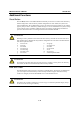
V+V-
SG
12-48V
SG: The Shielded Ground (sometimes called
Protected Ground) contact is the left most contact
of the 3-pin power terminal block connector when
viewed from the angle shown here. Connect the
SG wire to an appropriate grounded metal surface.
Connecting Data Transmission Cables
This section describes how to connect the EM-1220-DK carrier board to the network, serial
devices, and serial COM terminal.
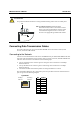
Connecting to the Network
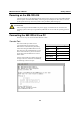
Connect one end of the Ethernet cable to the 10/100M Ethernet port of EM-1220-DK and the other
end of the cable to the Ethernet network. If the cable is properly connected, the EM-1220-DK will
indicate a valid connection to the Ethernet in the following ways:
y The top-right LED on the connector glows a solid green when connected to a 100 Mbps
Ethernet network.
y The top-left LED on the connector glows a solid orange when connected to a 10 Mbps
Ethernet network.
y The LEDs will flash when Ethernet packets are being transmitted or received.
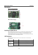
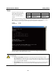
The 10/100 Mbps Ethernet LAN 1 and LAN 2 ports use 8-pin RJ45 connectors. Pinouts for these
ports are given in the following diagram.
8-pin RJ45
18
100 Mbps
indicator
10 Mbps
indicator
Pin Signal
1 ETx+
2 ETx-
3 ERx+
4 ---
5 ---
6 ERx-
7 ---
8 ---
1-9