UC-7110 Series User’s Manual www.moxa.com/product First Edition, September 2004 Moxa Technologies Co., Ltd. Tel: +886-2-8919-1230 Fax: +886-2-8919-1231 www.moxa.com support@moxa.com.tw (Worldwide) support@moxa.
UC-7110 Series User’s Manual The software described in this manual is furnished under a license agreement and may be used only in accordance with the terms of that agreement. Copyright Notice Copyright 2004 Moxa Technologies Co., Ltd. All rights reserved. Reproduction without permission is prohibited. Trademarks MOXA is a registered trademark of The Moxa Group. All other trademarks or registered marks in this manual belong to their respective manufacturers.
Table of Contents Chapter 1 Introduction ..................................................................................................1-1 Overview.................................................................................................................................. 1-2 Package Checklist .................................................................................................................... 1-2 Product Features .....................................................................
Upgrading the Kernel & Root File System .............................................................................. 4-5 Upgrading the User Directory.................................................................................................. 4-7 User Directory Backup—UC-7110 to PC................................................................................ 4-8 Loading Factory Defaults ........................................................................................................
1 Chapter 1 Introduction The MOXA UC-7110 Series of RISC-based Communication Platforms features two RS-232/422/485 serial ports, and dual 10/100 Mbps Ethernet ports, making these products ideal for embedded OS applications.
UC-7110 Series User’s Manual Introduction Overview The UC-7110 Series of RISC-based Communication Platforms are ideal for your embedded applications. UC-7110 comes with two RS-232/422/485 serial ports and dual 10/100 Mbps Ethernet LAN ports to provide users with a versatile communication platform. UC-7110 uses the ARM9 166 Mhz RISC CPU.
UC-7110 Series User’s Manual Introduction Product Specifications Hardware Specifications (UC-7110-LX) CPU ARM9-based 32-bit RISC CPU, 166 Mhz RAM 16 MB (12 MB of user programmable space) Flash 8 MB (4 MB of user programmable space) LAN Auto-sensing 10/100 Mbps x 2 LAN Protection Built-in 1.
UC-7110 Series User’s Manual Introduction Software Specifications (UC-7110-LX) Kernel µClinux Kernel 2.4.22 Protocol Stack ARP, ICMP, IPV4, TCP, UDP, FTP, Telnet, NTP, SNMP V1, HTTP, PPP, CHAP, PAP, NFS JFFS2 File System User Directory (Read / Write) ROMFS Kernel, Root File System (Read Only) Sash (V1.1.1) Simple OS shell command Pppd (V1.13) dial in/out over serial port daemon snmpd SNMP V1 Agent daemon busybox (V0.60.4) Linux normal command utility Tinylogin (V0.
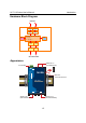
UC-7110 Series User’s Manual Introduction Hardware Block Diagram Ethernet Power Circuit LAN1 LAN2 PHY PHY S3C2500 ARM940T 166MHz 8MB Flash 16MB SDRAM MOXA MU150 MOXA MU150 Port 1 Port 2 RTC RS-232/422/485 Appearance Ethernet x 2 (10/100BaseTx) 12- 48 VDC V+ RESET LAN2 LAN1 12-48V Ready TX P1 RS-232 Console Terminal RX TX P2 RX UC-7110 Universal Communicator P1 RS-232/422/485 P2 Serial Port 1 (RS-232/422/485) Serial Port 2 (RS-232/422/485) 1-5
UC-7110 Series User’s Manual Introduction Dimensions V+ RESET LAN1 LAN2 12-48V 6 (0.24) 4 (0.16) Ready 12.5 (0.49) TX P1 RX TX 111 (4.31) P2 RX UC-7110 25 (0.98) Universal Communicator 21.3 (0.8) 7 (0.28) P1 RS-232/422/485 P2 47.3 (1.56) 26 (1.02) unit = mm (inch) 77 (3.03) 88 (3.46) 100 (4.
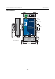
UC-7110 Series User’s Manual Introduction Installing UC-7110 Top-End View Reset Button Terminal Block Power Input RJ45 10/100 Mbps Ethernet Ports Nameplate View V+ RESET LAN1 LAN2 12-48V Ready TX P1 DIN-Rail screw hole RX TX P2 RX UC-7110 Universal Communicator P1 RS-232/422/485 Wallmount screw hole P2 Bottom-End View DB9 (male) Serial Ports 1-7
UC-7110 Series User’s Manual Introduction LED Indicators The following table explains the function of the five LED indicators located on UC-7110’s top panel. LED Name LED Color Ready Green Power is on and functioning normally. Green Serial port 1/2 is transmitting data. P1/P2 (Tx) Off P1/P2 (Rx) Yellow Off LED Function Serial port 1/2 is not transmitting data. Serial port 1/2 is receiving data. Serial port 1/2 is not receiving data.
UC-7110 Series User’s Manual Introduction Connecting the Power Connect the “live-wire” end of the 12-48 VDC power adaptor to UC-7110’s terminal block. If the power is properly supplied, the “Ready” LED will show a solid green color after a 25 to 30 second delay. Grounding UC-7110 Grounding and wire routing helps limit the effects of noise due to electromagnetic interference (EMI). Run the ground wire from the ground screw to the grounding surface prior to connecting devices.
UC-7110 Series User’s Manual Introduction The 10/100 Mbps Ethernet LAN 1 and LAN 2 ports use 8-pin RJ45 connectors. Pinouts for these ports are given in the following diagram. 8-pin RJ45 10 Mbps 100 Mbps indicator indicator 1 8 Pin 1 2 3 4 5 6 7 8 Signal ETx+ ETxERx+ ----ERx----- Connecting to a Serial Device Connect the serial cable between UC-7110 and the serial device(s). Serial ports P1 and P2 use male DB9 connectors, and can be configured for RS-232/422/485 by software.
UC-7110 Series User’s Manual Introduction Additional Functions Reset Button Press the “RESET” button continuously for more than 5 seconds to load the factory default configuration. After loading the factory default, the system will reboot automatically. The System Ready LED will be blinking for the first 5 seconds. We recommend that you only use this function if the software is not working properly.
UC-7110 Series User’s Manual Introduction Real Time Clock UC-7110’s real time clock is powered by a lithium battery. We strongly recommend that you do not replace the lithium battery without the help of Moxa’s support team. If the battery needs to be changed, contact the Moxa RMA service team for RMA service. ATTENTION The battery may explode if replaced by the incorrect type. To avoid this potential danger, always be sure to use the correct type of battery.
2 Chapter 2 Getting Started In this chapter, we explain the basic procedure for getting UC-7110 connected. This chapter covers the following topics: ! Powering on UC-7110 ! Connecting UC-7110 to a PC ! Configuring the Ethernet Interface ! Developing Your Applications " Installing the UC-7110 Tool Chain " Compiling Hello.
UC-7110 Series User’s Manual Getting Started Powering on UC-7110 Connect the SG wire to the Shielded Contact located on the upper left corner of the UC-7110, and then power on UC-7110 by connecting the power adaptor. It takes about 16 seconds for the system to boot up. Once the system is ready, the Ready LED will light up. ATTENTION After connecting UC-7110 to the power supply, it will take about 16 seconds for the operating system to boot up.
UC-7110 Series User’s Manual Getting Started Telnet If you know at least one of the two IP addresses and netmasks, then you can use Telnet to connect to UC-7110’s console. Default IP Address Default Netmask LAN 1 192.168.3.127 255.255.255.0 LAN 2 192.168.4.127 255.255.255.0 Telnet can be used locally by using a cross-over Ethernet cable to connect your computer to UC-7110, or over a LAN or the Internet. The default IP addresses and netmasks are shown above.
UC-7110 Series User’s Manual Getting Started Configuring the Ethernet Interface In this section we use the serial console to explain how to modify UC-7110’s network settings. 1. Change directories by issuing the command cd /mnt/etc. 2. Type the command vi rc to use VI Editor to edit the configuration file. The IP addresses for UC-7110’s LAN1 and LAN2 are given as ifconfig eth0 192.168.3.127 ifconfig eth1 192.168.4.127 as shown in the following figure.
UC-7110 Series User’s Manual 4. Getting Started Issue the vi “write” command to save the file, and then reboot. Since UC-7110 only reads the “rc” file when booting up, you must reboot (e.g., by issuing the vi reboot command) for the changes to take affect. ATTENTION You may reset the IP address immediately by issuing the command ifconfig eth0 192.168.5.127 (This will change the IP address of LAN1.
UC-7110 Series User’s Manual Getting Started Developing Your Applications Step 1: Connect UC-7110 to a Linux PC. Step 2: Install Tool Chain (GNU Cross Compiler & uClibc). Step 3: Configure cross compiler and uClibc environment variables. Step 4: Code & compile your program. Step 5: Download program to UC-7110 via FTP or NFS. Step 6: Debug the program. If the program is OK, proceed to Step 7. If the program needs to be modified, go back to Step 4.
UC-7110 Series User’s Manual Getting Started Compiling Hello.c The Tool Chain path is: PATH=/usr/local/arm-elf/bin:$PATH The UC-7110 CD includes several example programs. We use Hello.c to illustrate how to compile and run applications. Issue the following commands from your PC to compile Hello.c: # cd /tmp/ # mkdir example # cp –r /mnt/cdrom/example/* /tmp/example Go to the Hello subdirectory, and then issue the command #make to compile Hello.c. Finally, execute the program to generate hello and hello.
UC-7110 Series User’s Manual Getting Started Uploading “Hello” to UC-7110 To use FTP to upload hello to UC-7110, issue the following commands from the PC side: #ftp 192.168.3.127 ftp> cd /home ftp> bin ftp> put ./hello ftp> quit #telnet 192.168.3.
UC-7110 Series User’s Manual Getting Started Running “Hello” on UC-7110 To run the “Hello” program issue the following commands from the UC-7110 side: # chmod 755 hello #./hello The words “Hello World” will be printed on the screen. ATTENTION Be sure to calculate the amount of Flash Memory used by the User File System in the Flash ROM. Use the following command to determine the amount of memory being used: />df –h If the flash memory is full, you will no longer be able to save data in Flash ROM.
UC-7110 Series User’s Manual Getting Started Make File Example Code The following Makefile file example codes are copied from the Hello example from UC-7110’s CD-ROM. # Generated automatically from Makefile.in by configure. # $Id: Makefile.in,v 1.59 2002/03/24 22:20:19 jnelson Exp $ .SUFFIXES: .SUFFIXES: .o .c .
UC-7110 Series User’s Manual Getting Started ATTENTION There is another example that involves modifying the Makefile. If the target source code file is tcps1.c, then users should modify at least 4 places to replace hello with tcps1. Copy the Hello example’s Makefile to your source code target directory, and then modify it to work with your program. After that, follow the procedures outlined in the previous sections: Compiling Hello.c, Uploading “Hello” to UC-7110, and Running “Hello” on UC-7110.
3 Chapter 3 Software Package This chapter includes information about the software that is used with UC-7110 Series products.
UC-7110 Series User’s Manual Software Package UC-7110 Software Architecture The pre-installed µClinux Operating System used by UC-7110 follows the standard µClinux architecture, making programs that follow the POSIX standard easily ported to UC-7110 by using the GNU Tool Chain provided by www.uClinux.org. In addition to the Standard POSIX API, device drivers for the buzzer, and UART for the serial ports are also included.
UC-7110 Series User’s Manual Software Package and uses JFFS2 for the User Directory. The partition sizes are hard coded into the kernel binary. You must rebuild the kernel to change the partition sizes. The flash memory map is shown in the following table.
UC-7110 Series User’s Manual Software Package Although JFFS2 is a journaling file system, this does not preclude the loss of data. The file system will remain in a consistent state across power failures, and will always be mountable. However, if the board is powered down during a write, then the incomplete write will be rolled back on the next boot. Any writes that were already completed will not be affected. Additional information about JFFS2 is available at: http://sources.redhat.com/jffs2/jffs2.
UC-7110 Series User’s Manual Software Package bin dev busybox ttyS0 boa tty3 bf tty2 backupfs tty1 downramdisk tty0 upramdisk rom1 rom0 ptypf ptype ptypd ptypc ptypb ptypa ptyp9 ptyp8 ptyp7 ptyp6 ptyp5 ptyp4 ptyp3 ptyp2 ptyp1 ptyp0 ppp pio rtc ram1 ram0 null kmem mem cua0 console tty 3-5
4 Chapter 4 Configuring UC-7110 In this chapter, we describe how to configure UC-7110 Series products.
UC-7110 Series User’s Manual Configuring UC-7110 Enabling and Disabling Daemons The following daemons are enabled when UC-7110 boots up for the first time. ! ! ! ! ! ATTENTION SNMP Agent daemon: Telnet Server / Client daemon: Internet Daemons: FTP Server / Client daemon: WWW Server daemon: snmpd telnetd inetd ftpd boa How to enable/disable telnet/ftp server a. b. Edit the file ‘/etc/inetd.
UC-7110 Series User’s Manual Configuring UC-7110 Adding a Web Page Default Home Page address: /home/httpd/index.html You may change the default home page directory by editing the web server’s configuration file, located at: /home/httpd/boa.conf Type the following command to edit the boa.conf file: /mnt/home/httpd>vi boa.
UC-7110 Series User’s Manual Configuring UC-7110 Configuring Dial-in/Dial-out Service Dial-out Service Direct cable connection: ! ! Without username and password, use: />pppd connect ‘chat –v’ /dev/ttyM0 38400 crtscts& With username and password, use: />pppd connect ‘chat –v’ user xxxxx password xxxxx /dev/ttyM0 38400 crtscts& Connect Using a Modem: ! Use: />pppd connect ‘chat –v ATDT CONNECT’ user xxxxx password xxxxx /dev/ttyM0 38400 crtscts& ATTENTION If dial out fails, the pppd conne
UC-7110 Series User’s Manual Configuring UC-7110 How to Mount a Remote NFS Server Currently, UC-7110 only supports NFS (Network File System) clients. Users can open NFS service on a Linux PC for UC-7110 to push data to. UC-7110 can use NFS to mount a remote disk as a local disk for data or log purposes. 1. First, the NFS server must open an export directory and allow access to the IP address. Edit the file “/etc/exports” on your Linux PC, and then run the NFS daemon.
UC-7110 Series User’s Manual Configuring UC-7110 Use the built-in FTP client to download the uc7110-1.x.x.bin file from the PC. /ramdisk>ftp Login Name: xxxx Login Password: xxxx ftp> bin ftp> get uc7110-1.x.x.bin And then use the upkernel command to upgrade the kernel and root file system. /ramdisk>upkernel uc7110-1.3.11.
UC-7110 Series User’s Manual Configuring UC-7110 Upgrading the User Directory UC-7110 uses ROMFS (ROM File System), which is pre-set to READ only, for the kernel and root file system. UC-7110 provides a read/write user’s directory in the JFFS2 file system. By using this user’s directory, the system configuration file and user’s program can be stored on this disk. Search UC-7110’s CD-ROM for the latest user directory file, or download the file from www.moxa.com. The format is usrdisk-1.x.x.dsk.
UC-7110 Series User’s Manual Configuring UC-7110 User Directory Backup—UC-7110 to PC To enable the RAM disk, follow the commands given below: />upramdisk />cd ramdisk And then use the backupfs command to backup the file system. /ramdisk>backupfs /ramdisk/usrdisk-backup The file system will be backed up, and you can use ftp commands to transfer the usrdisk-backup to the FTP server on the PC.
UC-7110 Series User’s Manual Configuring UC-7110 Loading Factory Defaults The easiest way to “Load Factory Default” is with “Upgrade User directory.” Refer to the previous section “How to Upgrade User Directory” for an introduction. Mirroring the Application Program and Configuration For some applications, you may need to “Mirror” (or sometimes we said “Ghost”) one UC-7110’s user directory, and duplicate it to other UC-7110s. To do this, use the following recommended procedure: 1.
5 Chapter 5 UC-7110 Device API In this chapter, we discuss the Device API for the UC-7110 Series.
UC-7110 Series User’s Manual UC-7110 Device API RTC (Real Time Clock) The device node is located at /dev/rtc. UC-7110 supports µClinux standard simple RTC control. You must include to use these functions. 1. Function: RTC_RD_TIME int ioctl(fd, RTC_RD_TIME, struct rtc_time *time); Description: Reads time information from RTC. 2. Function: RTC_SET_TIME int ioctl(fd, RTC_SET_TIME, struct rtc_time *time); Description: Sets RTC time. Buzzer The device node is located at /dev/console.
6 Chapter 6 UC Finder UC-7110 comes with a UC Finder utility, which has the sole purpose of searching the LAN or intranet for UC-7110 units. For most of applications, it’s not easy to remember the IP addresses of Universal Communicators connected to the LAN. This is especially true for some problem solving and testing in the field. The UC Finder utility broadcasts messages over the LAN to search for IP addresses of Universal Communicators connected to the LAN.
UC-7110 Series User’s Manual UC Finder Windows UC Finder The following steps describe how to install UC Finder on a Windows PC. 1. Double click on the UC Finder installation program, Setup.exe, to start the installation. 2. When the Welcome to the UC Finder Setup Wizard window opens, click on Next to continue. 3. Check the Create a desktop icon box, and then click on Next to continue.
UC-7110 Series User’s Manual UC Finder 4. Check the Launch UC Finder checkbox to use UC Finder immediately after the installation has finished, and then click on Next to complete the installation. 5. When the UC Finder window opens, click on Broadcast Search to search for all Universal Communicators connected to the LAN.
UC-7110 Series User’s Manual UC Finder 6. The Searching window will show the Universal Communicators that have been located. You can click on Stop as soon as the Universal Communicator you are looking for is listed. 7. When the search is complete, the Broadcast Search window closes, and the Model, MAC Address, and IP Address of all Universal Communicators that were located will be listed in the UC Finder window.
UC-7110 Series User’s Manual UC Finder Linux ucfinder To use the Linux ucfinder utility, copy ucfinder from the CD-ROM to your Linux PC, and then use the command given below to start ucfinder. The ucfinder utility will automatically broadcast a message over your LAN network to find the IP address of all UC’s connected to the LAN. #.
A System Commands Appendix A busybox (V0.60.
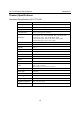
UC-7110 Series User’s Manual SNMP Agent with MIB II & RS-232 Like Group Network ping route netstat ifconfig tracerout tftp telnet ftp ping to test network routing table manager display network status set network IP address trace route tftp protocol user interface to TELNET protocol file transfer protocol kill killall ps kill process kill process by name report process status dmesg stty zcat mknod free date env clear reboot halt du gzip, gunzip hostname tar dump kernel log message set serial port dump
B SNMP Agent with MIB II & RS-232 Like Group Appendix B UC-7110 has a built-in SNMP (Simple Network Management Protocol) agent that supports RFC1317 RS-232 like group and RFC 1213 MIB-II. The following table lists the variable implementation for UC-7110. Note: UC-7110 does not support SNMP trap.
UC-7110 Series User’s Manual ip MIB ipForwarding ipDefaultTTL ipInReceives ipInHdrErrors ipInAddrErrors ipForwDatagrams ipInUnknownProtos ipInDiscards ipInDelivers ipOutRequests ipOutDiscards ipOutNoRoutes ipReasmTimeout ipReasmReqds ipReasmFails ipFragOKs ipFragFails ipFragCreates ipAddrTable ipAdEntAddr ipAdEntIfIndex ipAdEntNetMask ipAdEntBcastAddr ipAdEntReasmMaxSize ipRouteTable ipRouteDest ipRouteIfIndex ipRouteMetric1 ipRouteMetric2 ipRouteMetric3 ipRouteMetric4 ipRouteNextHop ipRouteType ipRoutePro
UC-7110 Series User’s Manual SNMP Agent with MIB II & RS-232 Like Group snmp MIB snmpInPkts snmpOutPkts snmpInBadVersions snmpInBadCommunityNames snmpInBadCommunityUses snmpInASNParseErrs snmpInTooBigs snmpInNoSuchNames snmpInBadValues snmpInReadOnlys snmpInGenErrs snmpInTotalReqVars snmpInTotalSetVars snmpInGetRequests snmpInGetNexts snmpInSetRequests snmpInGetResponses snmpInTraps snmpOutTooBigs snmpOutNoSuchNames snmpOutBadValues snmpOutGenErrs snmpOutGetRequests snmpOutGetNexts snmpOutSetRequests snmp
C FAQ for UC-7110 Appendix C FAQ 1 Why can I only use vfork( ),and am unable to use fork( )? Answer 1 uClinux only supports vfork( ). It does not support fork( ). Note that when using vfork( ), the parent process will hang until the son process calls an exec group API, or exits.
UC-7110 Series User’s Manual FAQ for Use the ‘flthdr’ utility (on a PC) to check the current stack size. FAQ 5 How do I compress an application program? Answer 5 UC7110’s kernel supports ZFLAT format files. This means that when you compile the program, you can add the compress option to reduce the size of the binary file. Doing so will reduce the required flash space on the user disk.
D Service Information Appendix D This appendix shows you how to contact Moxa for information about this and other products, and how to report problems. In this appendix, we cover the following topics.
UC-7110 Series User’s Manual Service Information MOXA Internet Services Customer satisfaction is our number one concern, and to ensure that customers receive the full benefit of our products, Moxa Internet Services has been set up to provide technical support, driver updates, product information, and user’s manual updates. The following services are provided E-mail for technical support................................support@moxa.com.tw World Wide Web (WWW) Site for product information: .................
UC-7110 Series User’s Manual Service Information Problem Report Form MOXA UC-7110 Series Customer name: Company: Tel: Fax: Email: Date: 1. Moxa Product: $ UC-7110 2. Serial Number: _________________ Problem Description: Please describe the symptoms of the problem as clearly as possible, including any error messages you see. A clearly written description of the problem will allow us to reproduce the symptoms, and expedite the repair of your product.
UC-7110 Series User’s Manual Service Information Product Return Procedure For product repair, exchange, or refund, the customer must: % Provide evidence of original purchase. % Obtain a Product Return Agreement (PRA) from the sales representative or dealer. % Fill out the Problem Report Form (PRF). Include as much detail as possible for a shorter product repair time. % Carefully pack the product in an anti-static package, and send it, pre-paid, to the dealer.