
Installation Guide
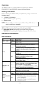
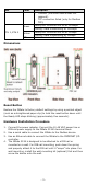
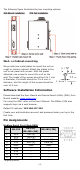

Table Of Contents

- 3 -
LED
Color
Description
3. Timeout (the slave device does not
respond).
4. TCP connection failed (only for Modbus
TCP).
ETH 1, ETH 2
Green
Steady ON: Ethernet link on at 100Mbps.
Blinking: Data transmitting at 100Mbps.
Amber
Steady ON: Ethernet link on at 10Mbps.
Blinking: Data transmitting at 10Mbps.
Off
Link is down or not connected.
Dimensions
Reset Button
Restore the MGate to factory default settings by using a pointed object
(such as a straightened paper clip) to hold the reset button down until
the Ready LED stops blinking (approximately five seconds).
Hardware Installation Procedure
1. Connect the power adapter. Connect the 12-48 VDC power line or
DIN-rail power supply to the MGate 5134’s terminal block.
2. Use a serial cable to connect the MGate to the Modbus device.
3. Use an Ethernet cable to connect the MGate to the PROFINET I/O
controller.
4. The MGate 5134 is designed to be attached to a DIN rail or
mounted on a wall. For DIN-rail mounting, push down the spring
and properly attach it to the DIN rail until it “snaps” into place. For
wall mounting, install the wall-mounting kit (optional) first and then
screw the device onto the wall.