AWK-1151C Series Quick Installation Guide Moxa AirWorks Version 1.0, September 2022 Technical Support Contact Information www.moxa.com/support 2022 Moxa Inc. All rights reserved.
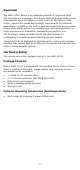
Overview The AWK-1151C Series is an industrial-grade Wi-Fi client with IEEE 802.11ac Wave 2 technology. This Series features dual-band Wi-Fi data transmissions up to 400 Mbps (2.4 GHz mode) or 867 Mbps (5 GHz mode), meeting the speed and flexibility requirements for industrial applications. In addition, the built-in dual band pass filter and the widetemperature design ensure the reliability and continuous operation in harsh environments. Meanwhile, backwards compatibility with 802.
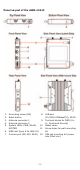
Panel Layout of the AWK-1151C 1. 2. 3. 4. 5. 6. 7. 8. Grounding screw (M5) Reset button Antenna connector 1 9. Antenna connector 2 System LEDs: PWR, WLAN, 10. SYSTEM 11. USB host (type A for ABC-02) Console port (RS-232, RJ45) 12.
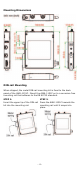
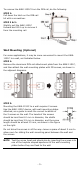
Mounting Dimensions DIN-rail Mounting When shipped, the metal DIN-rail mounting kit is fixed to the back panel of the AWK-1151C. Mount the AWK-1151C on to a corrosion-free mounting rail that adheres to the EN 60715 standard. STEP 1: STEP 2: Insert the upper lip of the DIN-rail Press the AWK-1151C towards the kit into the mounting rail. mounting rail until it snaps into place.
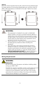
To remove the AWK-1151C from the DIN rail, do the following: STEP 1: Pull down the latch on the DIN-rail kit with a screwdriver. STEP 2 & 3: Slightly pull the AWK-1151C forward and lift it up to remove it from the mounting rail. Wall Mounting (Optional) For some applications, it may be more convenient to mount the AWK1151C to a wall, as illustrated below.
STEP 3: Once the screws are fixed into the wall, insert the screw heads through the large opening of the keyhole-shaped apertures, and then slide the AWK-1151C downwards, as indicated to the right. Tighten the screws for added stability. WARNING • • • • This equipment is intended to be used in a Restricted Access Location, such as an enclosed machine cabinet or chassis where only authorized service personnel or users can gain access.
Read and Follow These Guidelines: • Use separate paths to route wiring for power and devices. If power wiring and device wiring paths must cross, make sure the wires are perpendicular at the crossing point. NOTE • • • Do not run signal or communications wiring and power wiring in the same wire conduit. To avoid interference, wires with different signal characteristics should be routed separately.
Installations with Cable Extended Antennas for Outdoor Applications If an AWK device or its antenna is installed in an outdoor location, proper lightning protection is required to prevent direct lightning strikes to the AWK device. In order to prevent the effects of coupling currents from nearby lightning strikes, a lightning arrester should be installed as part of your antenna system. Ground the device, antenna, as well as the arrester properly to provide maximum outdoor protection for the device.
NOTE Before connecting the AWK-1151C DC power inputs, make sure the DC power source voltage is stable. • The wiring for the input terminal block shall be installed by a skilled person. • Wire type: Cu • Only use 16-28 AWG wire size. • Use only one conductor in a clamping point between the DC power source and the power input. ATTENTION If the AWK-1151C is connected to a motor or other similar type of equipment, be sure to use power isolation protection.
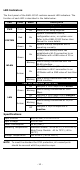
LED Indicators The front panel of the AWK-1151C contains several LED indicators. The function of each LED is described in the table below: LED PWR SYSTEM WLAN LAN Color State Description Front Panel LED Indicators (System) On Power is being supplied. Green Off Power is not being supplied. System initialization failure, configuration error, or system error. Red On Refer to the AWK-1151C Series User Manual for more details. System startup completed and is Green On operating normally.
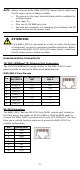
ATTENTION The AWK-1151C is NOT a portable mobile device and should be located at least 20 cm away from the human body. The AWK-1151C is NOT designed for the general public. To ensure that your AWK-1151C wireless network is safe and configured correctly, consult a well-trained technician to assist with the installation process. ATTENTION Use the appropriate antennas for your wireless setup: Use 2.4 GHz antennas when the AWK-1151C is configured for IEEE 802.11b/g/n.
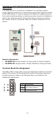
• Step 2: Connect the AWK to the notebook or PC via the AWK’s LAN port. The LED indicator on the AWK’s LAN port will light up when a connection is established. NOTE • If you are using an Ethernet-to-USB adapter, follow the instructions in the user manual provided with the adapter. Step 3: Set up the computer’s IP address. Choose an IP address for the computer that is on the same subnet as the AWK. Since the AWK’s default IP address is 192.168.127.253, and the subnet mask is 255.255.255.
• Step 5: Choose your country or region. Select your country or region from the drop-down list and click NEXT. • Step 6: Create a user account and password. Enter the username, password, and email address for your user account and click CREATE. NOTE The username and password are case-sensitive. After creating your account, you will be automatically redirected to the login screen.
• Step 7: Log in to the device. Enter your username and password and click LOG IN. The device will start initializing, this may take several seconds. Once the warning message has disappeared, you can log in using your username and password. First-time Quick Configuration After successfully accessing the AWK, refer to the appropriate subsection below to quickly set up a wireless network. NOTE Ensure that there are no IP address conflicts when you configure more than one AWK on the same subnet.
Configuring the AWK as a Client Set the operation mode of the AWK to Client mode. Go to Wi-Fi Wireless Settings and select Client from the Operation Mode drop-down list, set the SSID, and click Apply. For more detailed configurations, refer to the AWK-1151C Series User Manual.
Configuring the AWK as a Slave Set the operation mode of the AWK to Slave mode. Go to Wi-Fi Wireless Settings and select Slave from the Operation Mode drop-down list, set the SSID, and click Apply. For more detailed configurations, refer to the AWK-1151C Series User Manual. Certifications FCC/IC Statements Federal Communication Commission Interference Statement This equipment has been tested and found to comply with the limits for a Class A digital device, pursuant to Part 15 of the FCC Rules.
Radio Transmitters (Part 15) This device complies with part 15 of the FCC Rules. Operation is subject to the following two conditions: 1. This device may not cause harmful interference. 2. This device must accept any interference received, including interference that may cause undesired operation.
NOTE ANATEL When the device is installed outdoors, it is prohibited to use frequency bands U-NII-1 (5.15 - 5.25GHz) and U-NII-2A (5.25 - 5.35HGz).