
Installation Guide

- 5 -
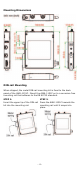
To remove the AWK-1151C from the DIN rail, do the following:
STEP 1:
Pull down the latch on the DIN
-rail
kit with a screwdriver.
STEP 2 & 3:
Slightly pull the
AWK-1151C
forward and lift it up to remove it
from the mounting rail.
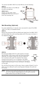
Wall Mounting (Optional)
For some applications, it may be more convenient to mount the AWK-
1151C to a wall, as illustrated below.
STEP 1:
Remove the aluminum DIN-rail attachment plate from the AWK-1151C,
and then attach the wall-mounting plates with M3 screws, as shown in
the adjacent diagrams.
STEP 2:
Mounting the
AWK-1151C to a wall requires 2 screws.
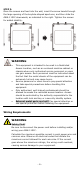
Use
the AWK-1151C device, with wall-mounting plates
attached, as a guide to mark the correct locations of
the
2 screws on the wall. The heads of the screws
should be less than 6.0 mm in diameter, the
shafts
should be less than 3.5 mm in diameter,
and the screw
length shoul
d be at least 15 mm,
as shown in the figure
on the right.
Do not drive the screws in all the way—leave a space of about 2 mm to
allow room for sliding the wall-mounting panel between the wall and
the screws.
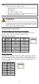
NOTE
Test the screw head and shank size by inserting the screws into
one of the keyhole shaped apertures of the wall
-mounting
plates before they are fixed to the wall.